AMIO with WinScript Live
An AMIO can be added to a WinScript Live script like any other device. Once added, I/O appears that can be used just like any local show controller I/O.
More information on WinScript Live can be found in the WinScript Live user's guide.
Setup
Add AMIO Device
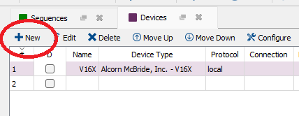
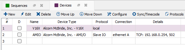
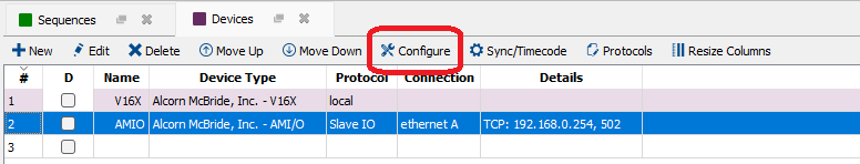
Open the Devices resource view. Click the New button to add a new device as seen in Figure 1.
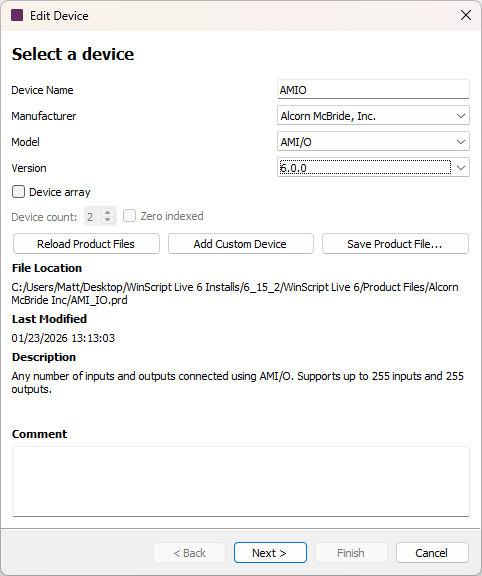
In the Device Name field, enter any name you'd like. This name will be the prefix for addressing the individual IO points. For example, naming the device "AMIO" will result in inputs with names that look like "AMIO.input1". These names will also appear as drop down selection options on the Inputs and Outputs resource windows.
Select the Make, Model and Version for the AMIO as shown in Figure 2 below.
Click Next.
Note
The version number you see may not be the same as in the image above.
Set Up the Connection
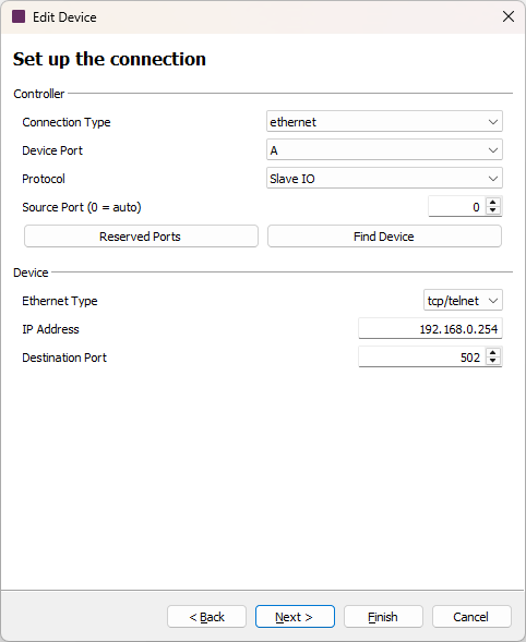
In the "Set up the connection" window, in the IP Address field in the Device section, specify the IP address of your AMIO as shown in Figure 3. By default, this address is 192.168.0.254.
Note
The "Find Device" feature can be accessed at any time by clicking on the Config tool button on the toolbar in the main devices view.
If you do not know the IP address, click the Find Device button. Find Device is only allowed if a show controller is also online and can be connected to in live mode.
It is not necessary to find the device while adding the AMIO to the script. This is done only for ease of use. Even if a valid IP address is not known, the necessary Inputs and Outputs resources will be added to the script. The device can be configured at a later time before testing begins.
For more details on the Find Device dialogs and their functions, see the Find Device section.
Click Next.
Define Inputs and Outputs
On the "Set up device variables" window, in the Inputs and Outputs fields, enter the desired number of inputs and outputs as shown in Figure 4.
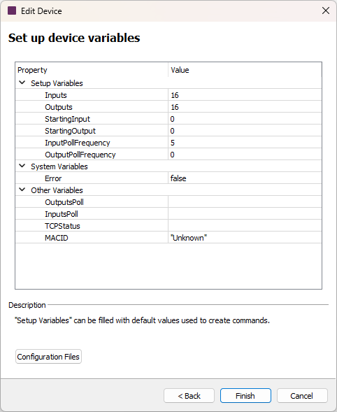
The Starting Input and Starting Output fields specify the input/output to start controlling. This is typically left at zero, but can be useful if multiple show controllers are controlling the same AMIO unit.
Note
The position of the output modules relative to the input modules has no effect on the Starting Input or Starting Output fields. Input and output modules can be arranged in any order. The Couplers recognize the terminals to which they are connected, and perform the assignment of the inputs and outputs automatically.
The InputPollFrequency is the frequency in frames at which the show controller will send a request for the value of the AMIO inputs. If set to 0, the inputs will not be polled. Set to 0 if you have an AMIO that only includes outputs.
The OutputPollFrequency is the frequency in frames at which the show controller will send a request for the value of the AMIO outputs. If set to 0, the outputs will automatically be polled for verification after every "set" of an output.
Click Finish. Your AMIO device should now be added to the list of WinScript Live devices as shown in Figure 5 below.
Using Inputs and Outputs
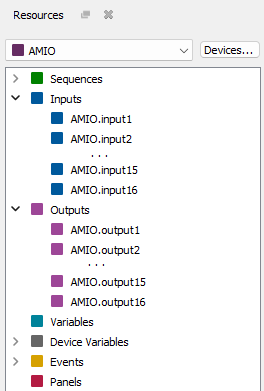
Input and Output resources are created based on the number of inputs and outputs specified when the AMIO device was added to the script. These resources can be viewed by clicking the drop-down menu at the top of the Resources window and selecting the AMIO device we just added as shown in Figure 6 below.
You can open the Input and Output resource views by double-clicking on either Inputs or Outputs in the Resource window, or by clicking Resources on the top menu bar then either Inputs or Outputs, or by using the hotkey CTRL+SHIFT+I for Inputs or CTRL+SHIFT+O for Outputs. These views allow you to configure your resources, like changing names, adding comments, or defining Init State On (for Outputs only).
You can drag the inputs onto Sequences to easily create Triggers, as shown in Figure 7 below. Click here for more information about Triggers.
Similarly, you can drag Outputs into the Events resource view for a Sequence to create an On event to turn on an output as shown in Figure 8 below.
Setting IP Address
This section describes setting the IP address using the BootP configuration with WinScript Live. For other methods of setting the IP address, see Getting Started
If the device is already added, proceed with the following instructions. Otherwise, follow the instructions for adding a device in Add AMIO Device above.
Start Configure Tool
From the Devices window, click on the Configure button with the AMIO device's row selected in the grid.
If you are already in Live Mode, the "ping" dialog appears. Otherwise, you will be prompted to go into Live Mode now. This will save your script and download it to the show controller.
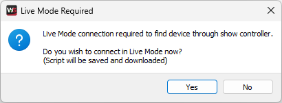
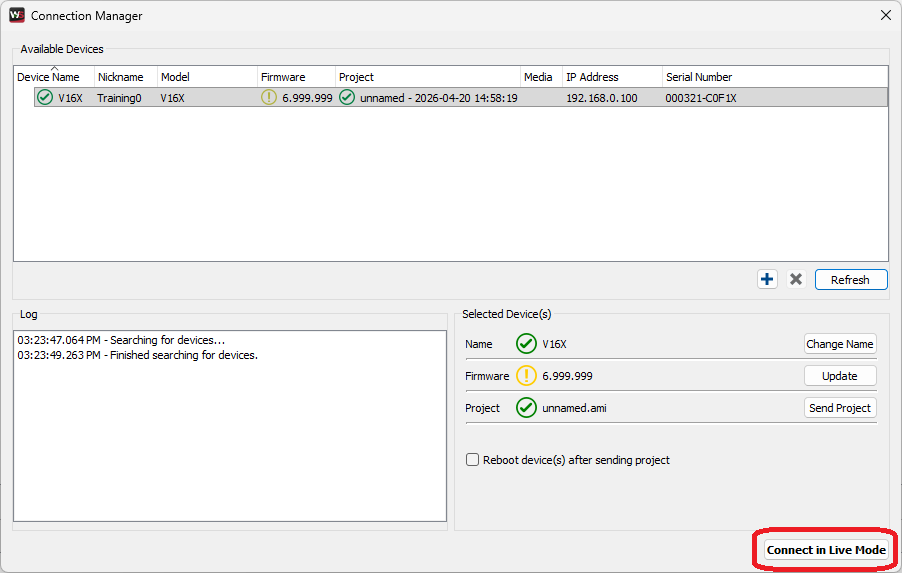
Click "Yes" to open the Connection Manager dialog box as shown in Figure 11. Click "Connect in Live Mode". Once in live mode, the "ping" dialog will appear.
Ping Device
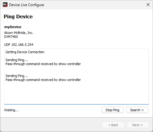
The Ping Device window will begin to ping your AMIO as shown in Figure 12.
Note
WinScript Live sends the ping through the show controller and not your computer. This means your show controller must be on the same network as the AMIO you are trying to ping, regardless of your computer's IP address.
If the Ping Device window shows "reply received", no further configuration is necessary. Your AMIO is ready to use with your show controller.
If the device is not found, proceed to the Find Device window by clicking Search or Next.
Find Device
The Find Device window will ping each IP address in the range defined in the IP Address Range fields at the top of the window via the show controller and will try to establish a response to the Modbus TCP command of "Poll Inputs" as shown in Figure 13.
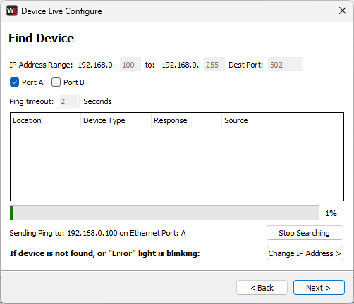
The Find Device window will only find the AMIO if the IP address is on the same subnet as your show controller.
If the device is found, select the device and click Next. You will then be prompted to choose the IP address to set. See the section Change Location for more information.
If the device is not found, click Next or Change IP Address and follow the instructions specified in the following section to reset the IP address.
Reset IP Address
To change address back to 0.0.0.0, the DIP switches must be toggled and at least one cold boot must take place.

Before the AMIO will appear, the IP address must be erased and the "ERROR" led on the front of the AMIO must be blinking red.
To do this, follow the on screen instructions (printed here):
- Set the DIP switches 1-8 to "ON" and power cycle
- The "ERROR" LED should continuously flash red
- If not flashing, flip DIP switches 1-8 to "OFF", power cycle and repeat step 1
- Click "Search"
Once the desired AMIO device appears in the list, select it and click Next to move to the Change Location window.
Note
If the device does not appear, make sure you are connected on the same local network and that the "ERROR" led is blinking red.
Change Location
Select the desired option for setting the IP address in either WinScript Live, on the AMIO itself, or in both as shown in Figure 15.
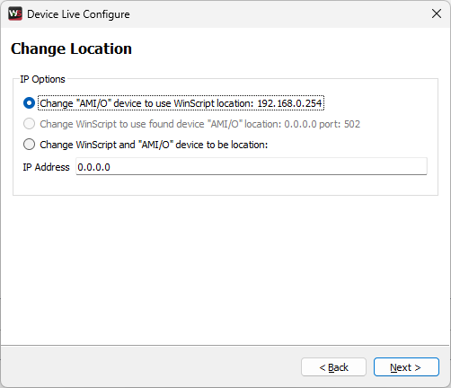
- Option 1: Change "AMIO" device to use WinScript Live location: This option should be used if you want to change the AMIO's IP address to match the address you have already specified in WinScript Live.
- Option 2: Change WinScript Live to use found device "AMIO" location: This option is only available if you have already set the IP address of the AMIO, and have found the device on the same network as your show controller. This will only change the WinScript Live script and not the AMIO.
- Option 3: Change WinScript Live and "AMIO" device to be location: Both the WinScript Live device IP address and the physical AMIO device are set to the IP address specified.
After clicking Next, a log will appear as the selected options are performed as shown in Figure 16.
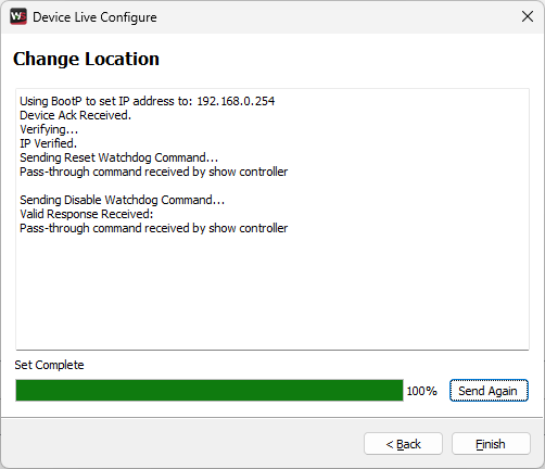
Depending on the options selected in the previous "IP Set" screen, actions will be performed on your script and/or your AMIO device. The watchdog will also be reset and disabled as part of this step.