Hardware Information
Overview
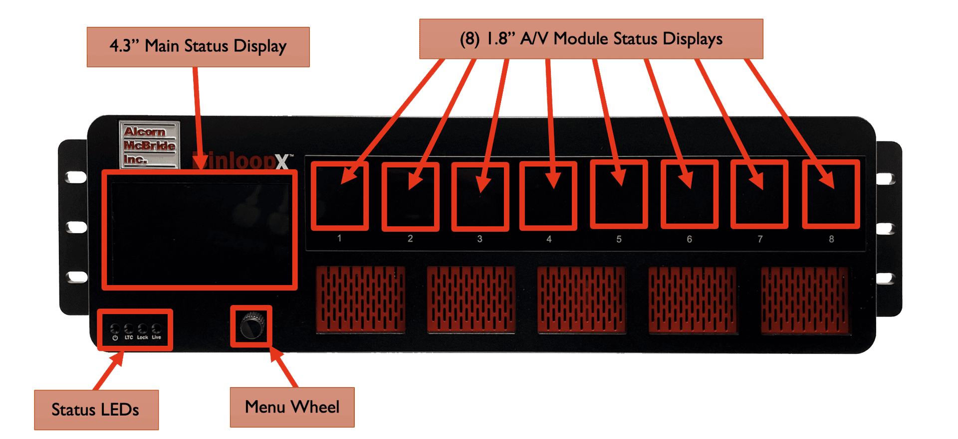
The BinloopX chassis includes a built-in 110-240VAC redundant power supply, 4.3" TFT status display, navigation wheel, status LEDs, BC-CON1 controller module, and 8 A/V module slots.

Display and Navigation
The front panel of BinloopX features a 12-line by 43-character TFT status display.

This display is primarily used to share application-specific information (i.e. "Status: Playing") from the show control script. However, this display also offers a full menu system that can be accessed by pushing the navigation wheel located just below the display.
To access the menu system, simply press in the navigation wheel. The wheel can then be rotated and pressed to browse the menu system, select items, and change settings.
Below, you will find a description of the menu items that are available from this interface.
Main Menu
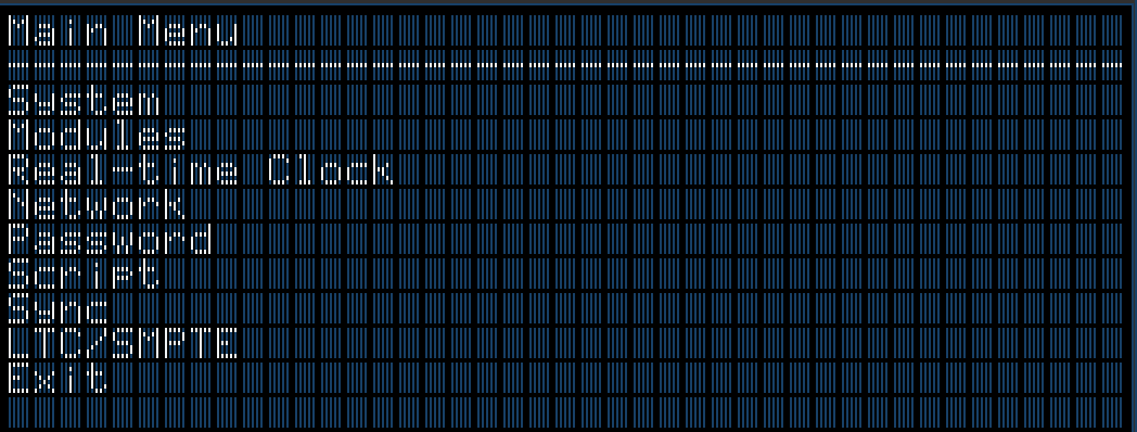
This menu provides access to the following sub-menus:
-
System -- Configure and monitor generic system status
-
Modules -- View status of installed modules
-
Real-Time Clock -- Configure and monitor real-time clock
-
Network -- Configure network interface
-
Password -- Configure front-panel lockout password
-
Script -- Monitor show control performance and script status
-
Sync -- Monitor sync system status
-
LTC/SMPTE -- Monitor the SMPTE LTC status
-
Exit -- Exit the menu
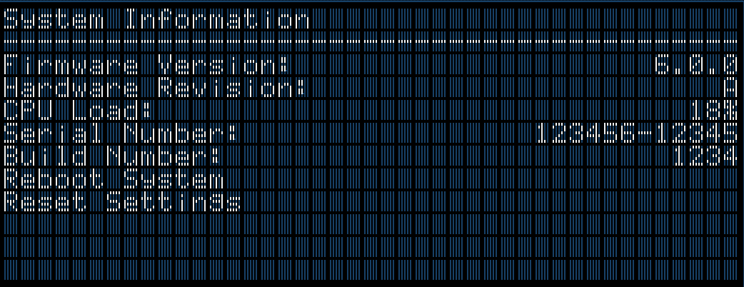
System Menu
-
Firmware Version -- Firmware version of BX-CON1 controller module
-
Hardware Revision -- Revision of BX-CON1 controller module hardware
-
Percent of Frame Used by Process -- Percent of frame time used by the show control script
-
Serial Number -- Chassis serial number
-
Uptime -- Elapsed time since start of show control script
-
Build Number -- Build revision of firmware
-
Reboot System -- Reboot controller and re-launch script
-
Reset Settings -- Reset all configuration data (i.e. network, device name, etc.) to factory defaults
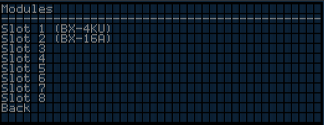
Modules Menu
-
Slot X -- Slot number containing model number of installed module
-
Back -- Return to the System Menu
Module Info

-
Model -- Model of installed module
-
Name -- Descriptive name of module (i.e. Main Theater)
-
Firmware Version -- Firmware version of module
-
Space Remaining -- Remaining media capacity of module
-
Media IP Address -- IP Address of Media Network port
-
Media Subnet Mask -- Subnet Mask of Media Network port
-
Media Gateway -- Gateway Address of Media Network port
-
Reboot Module -- Reboot module
-
Back -- Return to the Modules Menu
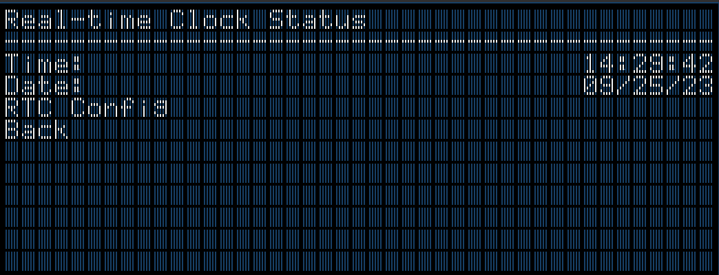
Clock Menu
-
Time -- Current system clock time
-
Date -- Current system clock date
-
RTC Config -- Used to set system clock time and date
Network Menu

-
IP Address -- View/Configure IP address
-
Subnet Mask -- View/Configure subnet mask
-
Gateway -- View/Configure gateway IP address
-
DNS -- View/Configure DNS address
Password Menu

-
Password Protect Front Panel -- Enable/Disable Password Protection
-
Set Password -- Set/Modify front panel password
Script Menu

-
Script Filename -- Currently active show control script
-
Script Edit Date -- Edit date of active show control script
-
Reload Script -- Selecting this reloads and restarts the show control script
-
Device Name -- Assigned text name of the BinloopX
-
Device ID -- Assigned ID number of the BinloopX
-
Device Nickname -- Optional text nickname of the BinloopX
-
View Watches -- View watch list that is generated within the WinScript project
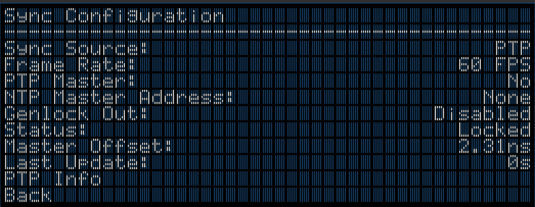
Sync Menu
-
Sync Source -- The configured sync source
-
Frame Rate -- Master frame rate of BinloopX
-
PTP Master -- Displays 'Yes' if BinloopX is operating as a PTP Master
-
NTP Master Address -- Show the NTP Server Address if BinloopX is operating as NTP Server
-
Genlock Out -- State of Genlock Output
-
Status -- Current state of BinloopX with configured Sync Source
-
Master Offset -- Accuracy of synchronized clocks
-
Last Update -- Time that has passed since last sync update
-
PTP Info -- Detailed status of PTP synchronization system
SMPTE/LTC Menu

-
Status -- Generate/Read, Current LTC value, framerate, and active status
-
Start SMPTE -- Enables the SMPTE interface to either Generate or Read based on configuration
Indicator LEDs
This BinloopX has a very simple set of indicator LEDs located in the lower left corner of the front-panel.

Power -- ON whenever power is applied to the unit and the power switch is on
LTC -- ON whenever SMPTE LTC is being actively generated or read
Lock -- ON whenever the sync system is locked to the configured sync source
Live -- ON whenever WinScript Live is connected to the unit
Connectors
Power Input
These connectors are used to supply the BinloopX with redundant power. This is a universal power supply that supports 110-240VAC at a frequency between 50-60Hz. These connectors use standard IEC320 C14 sockets, which can be used with IEC320 C13 cables that are suitable for your region.

A power switch is located just below the power supply, which is used to power the unit ON or OFF.
When both power supply modules are operating properly, a status LED directly next to the power connections will illuminate. If a power supply module is removed or fails, it's LED will turn off. Also, a loud and purposefully obnoxious alarm will sound to notify you that the unit is no longer operating with redundant power. This alarm can be silenced by pressing the recessed 'Silence The Faulty Unit' button. This STFU button is located just above the top power connector. Alternatively, inserting a functioning power supply module will also silence the alarm.
These modules can be removed by pushing UP on the small black lever located at the bottom-left of the module while pulling the metal handle away from the BinloopX unit. See the Accessories section of this manual for information on ordering a replacement module.
Two IEC Type B power cords are included with the BinloopX.
Connector Information
| Power Connector | |
|---|---|
| Connector Type | IEC320 C14 |
| Mating Plug | IEC320 C13 |
Network
The main network interface for the BinloopX is located on the back of the controller module and is simply labeled Network. This interface requires a standard RJ45 connection and serves as the main link between a computer running WinScript Live and the BinloopX. It is the primary interface used to store/retrieve script files as well as media content with the BinloopX.

Connector Information
| Network Connector | |
|---|---|
| Connector Type | RJ45 Female |
| Mating Plug | RJ45 Male |
Some portions of the network interface, such as FTP access, are protected with a configurable username and password. By default, these credentials are configured to:
| Default FTP Credentials | |
|---|---|
| User Name | admin |
| Password | password |
Genlock
These BNC connectors are used to connect external devices to the BinloopX genlock interface. When configured to lock to an external video sync source, the BinloopX will expect to see a Tri-level, Blackburst, or Composite Sync input on the 'IN' connector.
Regardless of the source sync reference, the BinloopX will always output a Composite Sync genlock signal on the 'OUT' connector. This allows external genlock devices like cameras, video servers, show controllers, etc. to lock and synchronize directly to the A/V clocks generated within BinloopX.

Connector Information
| Sync Connectors | |
|---|---|
| Connector Type | BNC Female |
| Mating Plug | BNC Male |
Digital Inputs
These 8-pin terminal-style connectors provide access to 8 discrete digital inputs that can be used as show control triggers within your BinloopX script. Each input has two contacts and can be software-configured within the WinScript Live project for two modes of operation; contact closure or voltage.
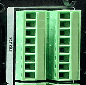
Connector Information
| Input Connector | |
|---|---|
| Connector Type | Phoenix 1843130 |
| Mating Plug | Phoenix 5447926 |
| Recommeded Wire | 18 AWG Stranded |

| Inputs (Left) | Inputs (Right) | |||
|---|---|---|---|---|
| Input 4 (+) | L1 | Input 8 (+) | R1 | |
| Input 4 (-) | L2 | Input 8 (-) | R2 | |
| Input 3 (+) | L3 | Input 7 (+) | R3 | |
| Input 3 (-) | L4 | Input 7 (-) | R4 | |
| Input 2 (+) | L5 | Input 6 (+) | R5 | |
| Input 2 (-) | L6 | Input 6 (-) | R6 | |
| Input 1 (+) | L7 | Input 5 (+) | R7 | |
| Input 1 (-) | L8 | Input 5 (-) | R8 |
Serial/GPS
These 7-pin terminal-style connectors provide access to the Serial control and GPS features. This includes two serial ports that can be configured to operate in either RS232 or RS422 modes. One of these ports is a dedicated GPS interface used for highly accurate clock synchronization and triggering based upon geographic location. The second port is multi-purpose and can be configured for RS232/RS422 control of the BinloopX.
Mating Plugs for these connectors ship pre-installed with the BinloopX.

Connector Information
| Serial/GPS Connector | |
|---|---|
| Connector Type | Phoenix 1843127 |
| Mating Plug | Phoenix 5447913 |
| Recommended Wire | 18 AWG Stranded |

| Serial Port | GPS Port | |||
|---|---|---|---|---|
| Ground | L1 | GPS PPS IN | R1 | |
| Serial RS232 TX | L2 | GPS RS232 TX | R2 | |
| Serial RS422 TX(-) | L2 | GPS RS422 TX(-) | R2 | |
| Serial RS422 TX(+) | L3 | GPS RS422 TX(+) | R3 | |
| Serial RS422 RX(-) | L4 | GPS RS422 RX(-) | R4 | |
| Serial RS232 RX | L5 | GPS RS232 RX | R5 | |
| Serial RS422 RX(+) | L5 | GPS RS422 RX(+) | R5 | |
| Ground | L6 | GPS Power (+5VDC) | R6 | |
| Ground | L7 | Ground | R7 |
NOTE: The GPS Power output supplies +5VDC and has an inline self-healing polymer fuse rated for 200mA.
NOTE: The GPS PPS input is designed to accept a TTL-level (5V) pulse at a frequency of 1HZ.
SMPTE LTC
These 3-pin terminal-style connectors provide access to the SMPTE Timecode (LTC) input and output.
Mating Plugs for these connectors ship pre-installed with the BinloopX.

Connector Information
| SMPTE LTC Connector | |
|---|---|
| Connector Type | Phoenix 1843088 |
| Mating Plug | Phoenix 5447874 |
| Recommeded Wire | 18 AWG Stranded |

Pinouts
| LTC OUT | LTC IN | |||
|---|---|---|---|---|
| LTC OUT (+) | L1 | LTC IN (+) | R1 | |
| LTC OUT (-) | L2 | LTC IN (-) | R2 | |
| LTC OUT (SHIELD) | L3 | LTC IN (SHIELD) | R3 |