Product Features
The show control feature set includes:
- Flexible configurations
- Ethernet TCP/IP
- Up to 64 I/O
- DIN-rail mountable
- Sleek form factor
- Easy to wire
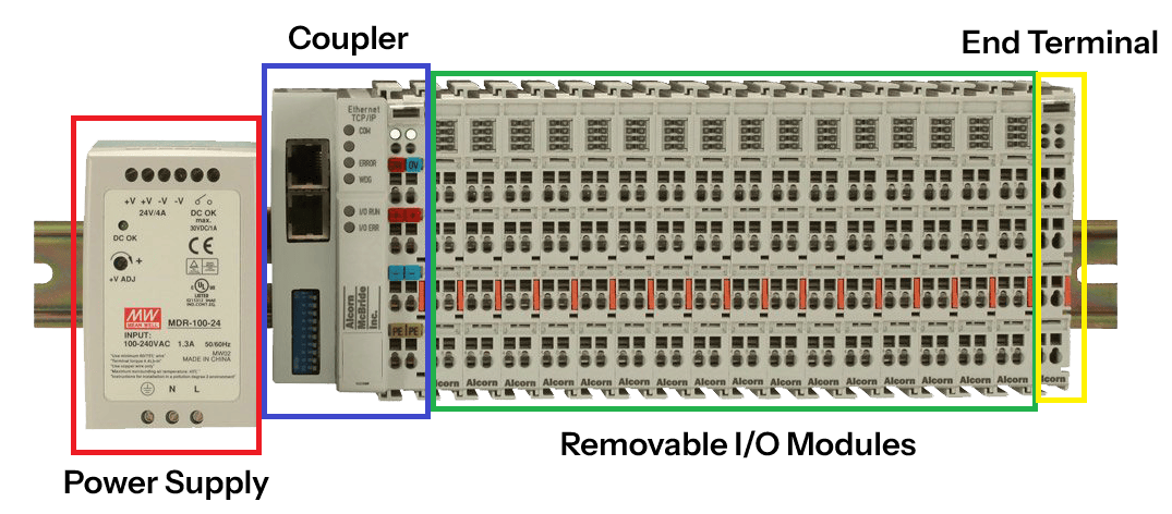
Each AMIO comprises a Coupler, a power supply, removable I/O modules, and an end terminal. These components are detailed in the sections below.
Coupler
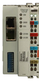
The AMIO-COUP, or Coupler, as shown in Figure 2, is the network communication device that provides communication between the show controller and the individual I/O modules.
Ethernet Control Interface
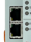
The Coupler features two RJ45 Ethernet ports as shown in Figure 3 that comprise the Ethernet Control Interface. Each port operates as a 2-channel switch running at 10/100T. The AMIO can be configured to use a line topology or star topology.
Ethernet Status LEDs
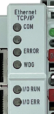
The Coupler features two sets of LEDs. The first, on the left, as shown in Figure 4, indicate the status of the Ethernet Control Interface as shown in Table 1.
| LED | Description |
|---|---|
| COM | On/blinking: communication established over Ethernet Control Interface |
| Off: no communication | |
| (Blank) | Blank LED not used |
| ERROR | Slow flashing: DHCP or BootP is active but has not yet received an IP address |
| Rapid flashing (5 times, only when switching on): the Coupler is addressed with ARP | |
| WDG | On: Watchdog timer error or Watchdog timer is set |
| Off: no current Ethernet Control Interface communication or no error | |
| I/O Run | Diagnostic LED for error |
| I/O Error | On: goes off after power up, could also indicate a device on the same network with the same IP address |
| Blinking: indicates error in I/O module(s) | |
| Off: no errors |
Voltage Status LEDs

On the upper right-hand side of the Coupler are two more green LEDs that indicate the supply voltage as shown in Figure 5. The left LED indicates the presence of the 24V supply. The right LED indicates the presence of the supply to the power contacts.
Configuration DIP Switches
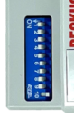
The Coupler features a set of 10 DIP switches as shown in Figure 6 which are used to configure IP address settings as shown in Table 2.
| DIP Switch | Description |
|---|---|
| SW1-SW8 | Used to determine if IP adress is saved on reboot (when using WinScript Live or BootP IP set method). |
| ON: IP address is saved after next cold start. | |
| OFF: IP address is not saved after next cold start. | |
| To erase saved IP address (and set again using WinScript Live) flip these to "OFF", reboot, and then flip back to "ON" (if IP address save is desired). | |
| SW9 | ON: IP address is configured using BootP server (WinScript Live) |
| OFF: IP address is configured using DHCP server | |
| SW10 | ON: IP address is configured using DHCP server |
| OFF: IP address is configured using BootP (WinScript Live) |
Watchdog (WDG)
The watchdog is a timer used for communication purposes. We deactivate this feature by default. See Troubleshooting for information on how to disable the watchdog if necessary.
Power Supply
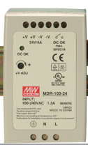
Every AMIO comes with a power supply. The power supply is a 96W 24V/4A supply. See Getting Started on how to connect the power supply.
Removable I/O Modules
See Getting Started on how to connect and use each I/O module.
Input Module

The AMIO-4INEXP, or Input Module, provides the AMIO with four (4) digital inputs.
This module is included with some of our AMIO kits depending on the configuration. This part is also available for purchase as a replacement in case the original components are lost or damaged.
Output Module

The AMIO-4OUTEXP, or Output Module, provides the AMIO with four (4) digital outputs.
This module is included with some of our AMIO kits depending on the configuration. This part is also available for purchase as a replacement in case original components are lost or damaged.
Power Insertion Module

The AMIO-PIM, or Power Insertion Module, can be inserted into your AMIO bus to provide 2A of additional output current.
End Terminal

Like every great journey, each AMIO too must end. This is done with an End Terminal. Additional I/O modules can be inserted before the end terminal. Release the end terminal by pulling on orange tab.