Hardware Information
Overview
RidePlayer has quite an assortment of dedicated hardware for the purpose of configuration, status monitoring, and interfacing to other hardware. This section covers these features in more detail.

Display and Navigation
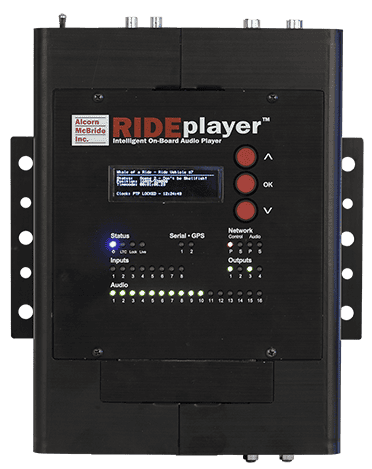
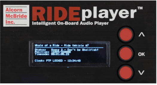
The top panel of RidePlayer features an 8-line by 42-character OLED status display. This display is primarily used to share application-specific information (i.e. “Location: Scene 2”) from the show control script. However, this display also offers a full menu system that can be accessed using the navigation buttons located adjacent to the display
Below, you will find a description of the menu items that are available from this interface.
Main Menu
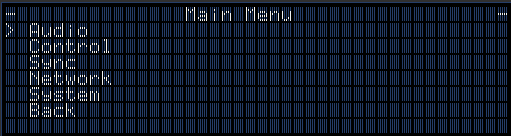
This menu provides access to the following sub-menus:
-
Audio -- Monitor and control audio interface
-
Control -- Monitor show control performance and script status
-
Sync -- Monitor sync system status
-
Network -- Configure network interface
-
System -- Configure and monitor generic system status
-
Exit -- Exit the menu
Audio Menu
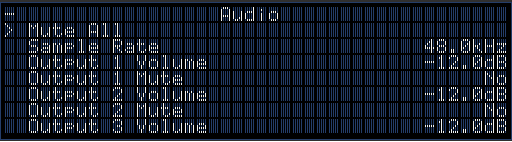
This menu provides access to the following sub-menus:
-
Mute All -- Mute/Unmute all audio outputs
-
Sample Rate -- View current audio sample rate (44.1KHz or 48.0KHz)
-
Output Volume -- Set volume level of individual output (-128dB->0dB)
-
Output Mute -- Mute/Unmute individual output
Control Menu
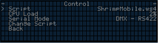
-
Script -- View currently active show control script
-
CPU Load -- View current load of show control processor
-
Serial Mode -- View mode of operation for multi-purpose serial port
-
Change Script -- Select a new active script file
Sync Menu
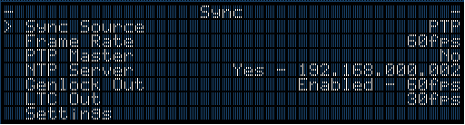
-
Sync Source -- The configured sync source
-
Frame Rate -- Master frame rate of RidePlayer
-
PTP Master -- Displays 'Yes' if RidePlayer is operating as a PTP Master
-
NTP Server -- Show the NTP Server Address if RidePlayer is operating as NTP Server
-
Genlock Out -- State of Genlock Output
-
LTC Out -- View operating frame rate of SMPTE LTC interface
-
PTP Info -- View detailed information about PTP status
-
Sync Status -- Time that has passed since last sync update
Network Menu
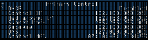

-
DHCP -- Enable/Disable DHCP network configuration
-
Control IP -- View/Configure Show Control IP address
-
Media/Sync IP -- Media/Sync IP address (Primary Only - Used for NTP/PTP sync and media file transfer)
-
Subnet Mask -- View/Configure subnet mask
-
Gateway -- View/Configure gateway IP address
-
DNS -- View/Configure DNS address
-
Control MAC -- View MAC address for Show Control Ethernet interface
-
Media/Sync MAC -- View MAC address for Media/Sync Ethernet interface
-
Link -- Current link status of network port
System Menu
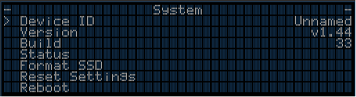
-
Device ID -- Shows the user-assigned name of the RidePlayer unit (i.e. “RV[1]”)
-
Version -- Firmware version of unit
-
Build -- Build revision of firmware
-
Status -- View status info such as temperature, fan speed, input voltage, etc.
-
Format SSD -- Erase and Format internal SSD media
-
Reset Settings -- Reset all configuration data (i.e. network, device name, etc.) to factory defaults
-
Reboot -- Reboot RidePlayer and re-launch script
Indicator LEDs
The top-panel of RidePlayer has a full set of indicator LEDs to provide an overall status of different features of the device.

Status LEDs
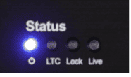
Power -- ON whenever power is applied to the unit and the power switch is on
LTC -- ON whenever SMPTE LTC is being actively generated or read
Lock -- ON whenever the sync system is locked to the configured sync source
Live -- ON whenever WinScript Live is connected to the unit
Serial - GPS

These indicators blink to indicate activity on either the GPS serial port, or the multi-purpose serial port.
Network
The network indicator LEDs are located in the top right section of the top-panel.

These indicators display both network link and activity for all of the Network ports.
| LED State | Description |
|---|---|
| OFF | No Network Link |
| SOLID ORANGE | Network link active – No network activity detected |
| BLINKING ORANGE | Network link active – Network activity detected |
Inputs
The input indicator LEDs are located in the middle left section of the top-panel.
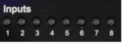
These are digital inputs that can be used to trigger show control events. These inputs can be configured via software to accept contact-closure or voltage triggers.
The table below defines the behavior of the indicator LEDs:
| LED State | Description |
|---|---|
| OFF | Inactive – No contact closure detected or voltage input is <9VDC |
| GREEN | Active – Contact closure detected or voltage input is 9-24VDC |
Outputs
The output indicator LEDs are located in the middle right section of the top-panel.
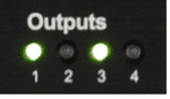
These are dry-contact relay outputs that are rated to 900mA and protected with inline self-healing polymer fuses. These relays are normally open (NO) and both relay contacts (COMMON = C, and NORMALLY OPEN = NO) are accessible for each output.
The table below defines the behavior of the indicator LEDs:
| LED State | Description |
|---|---|
| OFF | Inactive – Relay contact is OPEN |
| GREEN | Active – Relay contact is CLOSED |
Audio
The Audio Status indicator LEDs are located in the bottom section of the top-panel.
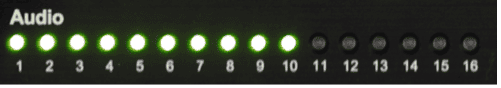
These indicators display the status of all 16 audio outputs. This includes playback activity and audio mute status.
| LED State | Description |
|---|---|
| OFF | No Audio Playback |
| GREEN | Audio playback in progress |
| RED | Audio output is MUTED |
Connectors
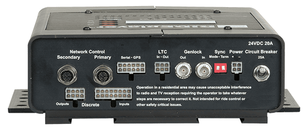
Power Input
This connector is used to power the RidePlayer. While this unit will operate with a power source between 9-28VDC, we recommend 24VDC to achieve maximum output power for the built-in amplifiers. This input includes a built-in 25A circuit breaker switch.

Connector Information
| Power Connector | |
|---|---|
| Connector Type | 2x4 Molex Mini-Fit Jr. |
| Mating Plug | Molex 0039012040 |
| Mating Pins | Molex 0039000185 |
| Recommended Wire | 18 AWG Stranded |
Pinouts
Plug pinout (Wire-Side View)
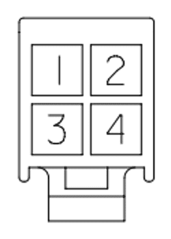
| Power | |
|---|---|
| PWR (+) | 1 |
| GND (-) | 2 |
| PWR (+) | 3 |
| GND (-) | 4 |
Network Control
RidePlayer has two Ethernet ports dedicated for control activities. The Primary port provides access to load a configuration and content from WinScript. The Primary port occupies two IP addresses; one for network synchronization (PTP and NTP) and media transfer, and another for device monitoring and control. The Secondary port only has a single IP address and can only be used for device monitoring and control.
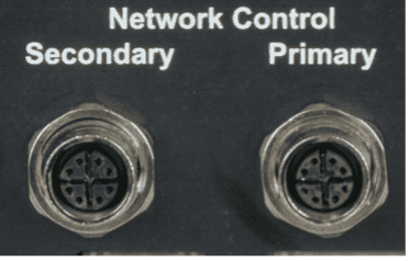
Connector Information
| Network Connector | |
|---|---|
| Connector Type | M12 X-Coded Female |
| Mating Plug | M12 X-Coded Male |
Some portions of the network interface, such as FTP access, are protected with a configurable username and password. By default, these credentials are configured to:
| Default FTP Credentials | |
|---|---|
| User Name | admin |
| Password | password |
Network Audio
RidePlayer distributes audio using the Dante and AES67 network audio standards. Both of these standards support redundant networks, which is why we have designed this module to provide both a Primary and Secondary audio network. Both of these interfaces utilize a standard RJ45 connection that you use to patch into your Dante or AES67 audio network.
Once connected, this network audio interface can be configured using the Audinate Dante Controller software. This application provides the ability to configure IP settings, name outputs, create Dante/AES67 flows, and route transmitters to receivers. To learn more about how to configure the network audio interface, be sure to read the Network Audio section.
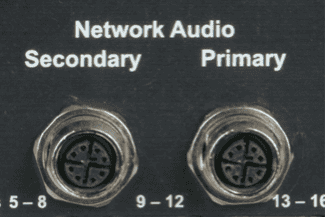
Connector Information
| Network Connector | |
|---|---|
| Connector Type | M12 X-Coded Female |
| Mating Plug | M12 X-Coded Male |
Genlock
These BNC connectors are used to connect external devices to the RidePlayer genlock interface. When configured to lock to an external video sync source, the RidePlayer will expect to see a Tri-level, Blackburst, or Composite Sync input on the 'IN' connector.
Regardless of the source sync reference, the RidePlayer will always output a Composite Sync genlock signal on the 'OUT' connector. This allows external genlock devices like cameras, video servers, show controllers, etc. to lock and synchronize directly to the A/V clocks generated within RidePlayer.
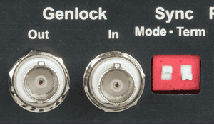
Connector Information
| Sync Connectors | |
|---|---|
| Connector Type | BNC Female |
| Mating Plug | BNC Male |
DIP Switch Information
| Termination Switch | |
|---|---|
| ON (UP) | 75 Ohm Termination |
| OFF (DOWN) | No Termination |
| Sync Type Switch | |
|---|---|
| ON (UP) | Blackburst/Tri-level |
| OFF (DOWN) | C-Sync |
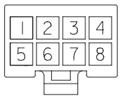
Digital Inputs
These 8-pin terminal-style connectors provide access to 8 discrete digital inputs that can be used as show control triggers within your RidePlayer script. Each input has two contacts and can be software-configured within the WinScript Live project for two modes of operation; contact closure or voltage.
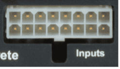
Connector Information
| Input Connector | |
|---|---|
| Connector Type | 2x8 Molex Mini-Fit Jr. |
| Mating Plug | Molex 0039012160 |
| Mating Pins | Molex 0039000073 |
| Recommended Wire | 18 AWG Stranded |
Pinouts
Plug pinout (Wire-Side View)
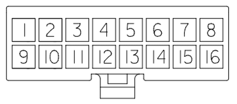
| Inputs 1-4 | Inputs 5-8 | |||
|---|---|---|---|---|
| Input 1 (+) | 1 | Input 5 (+) | 5 | |
| Input 1 (-) | 9 | Input 5 (-) | 13 | |
| Input 2 (+) | 2 | Input 6 (+) | 6 | |
| Input 2 (-) | 10 | Input 6 (-) | 14 | |
| Input 3 (+) | 3 | Input 7 (+) | 7 | |
| Input 3 (-) | 11 | Input 7 (-) | 15 | |
| Input 4 (+) | 4 | Input 8 (+) | 8 | |
| Input 4 (-) | 12 | Input 8 (-) | 16 |
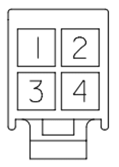
Digital Outputs
The RidePlayer is equipped with 4 discrete dry-contact relay outputs that are rated to 900mA and protected with inline self-healing polymer fuses. These relays are normally open (NO) and both relay contacts (COMMON = C, and NORMALLY OPEN = NO) are accessible for each output.

Connector Information
| Output Connector | |
|---|---|
| Connector Type | 2x4 Molex Mini-Fit Jr. |
| Mating Plug | Molex 0039012080 |
| Mating Pins | Molex 0039000073 |
| Recommended Wire | 18 AWG Stranded |
Pinouts
Plug pinout (Wire-Side View)
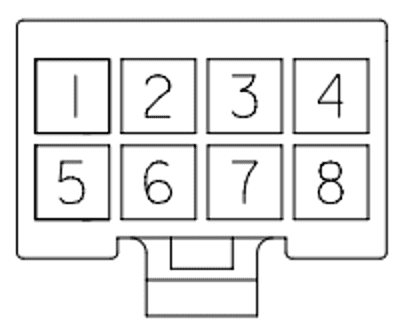
| Outputs | |
|---|---|
| Output 1 (+) | 1 |
| Output 1 (-) | 5 |
| Output 2 (+) | 2 |
| Output 2 (-) | 6 |
| Output 3 (+) | 3 |
| Output 3 (-) | 7 |
| Output 4 (+) | 4 |
| Output 4 (-) | 8 |
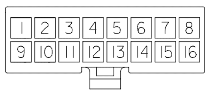
Serial/GPS/DMX
This connector provides access to the Serial Control, GPS, and DMX features. This includes two serial ports that can be configured to operate in either RS232 or RS422 modes. One of these ports is a dedicated GPS interface used for highly accurate clock synchronization and triggering based upon geographic location. The second port is multi-purpose and can be configured for DMX lighting control or for generic serial control of RS232/RS422 devices.
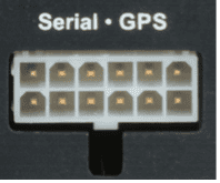
Connector Information
| Serial/GPS/DMX Connector | |
|---|---|
| Connector Type | 2x4 Molex Mini-Fit Jr. |
| Mating Plug | Molex 0039012120 |
| Mating Pins | Molex 0039000073 |
| Recommended Wire | 18 AWG Stranded |
Pinouts
Plug pinout (Wire-Side View)

| Serial (RS-232) | |
|---|---|
| Serial RS232 TX | 9 |
| Serial RS232 RX | 1 |
| Ground | 7 |
| Serial (RS-422) | |
|---|---|
| Serial RS422 TX(-) | 9 |
| Serial RS422 TX(+) | 2 |
| Serial RS422 RX(-) | 8 |
| Serial RS422 RX(+) | 1 |
| Ground | 7 |
| Serial (DMX512) | |
|---|---|
| DMX Out(-) | 9 |
| DMX Out(+) | 2 |
| Ground | 7 |
| GPS Port | |
|---|---|
| GPS PPS IN | 6 |
| GPS RS232 TX | 12 |
| GPS RS422 TX(-) | 12 |
| GPS RS422 TX(+) | 5 |
| GPS RS422 RX(-) | 11 |
| GPS RS232 RX | 4 |
| GPS RS422 RX(+) | 4 |
| GPS Power (+5VDC) | 10 |
| Ground | 3 |
NOTE: The GPS Power output supplies +5VDC and has an inline self-healing polymer fuse rated for 200mA.
SMPTE LTC
This connector provides access to the SMPTE Timecode (LTC) input and output.
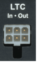
Connector Information
| SMPTE LTC Connector | |
|---|---|
| Connector Type | 2x3 Molex Mini-Fit Jr. |
| Mating Plug | Molex 0039012060 |
| Mating Pins | Molex 0039000073 |
| Recommended Wire | 18 AWG Stranded |
Pinouts
Plug pinout (Wire-Side View)
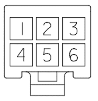
| LTC OUT | LTC IN | |||
|---|---|---|---|---|
| LTC OUT (+) | 4 | LTC IN (+) | 6 | |
| LTC OUT (-) | 1 | LTC IN (-) | 3 | |
| LTC OUT (SHIELD) | 5 | LTC IN (SHIELD) | 2 |
Speaker Outputs
This is where you connect speakers being driven from the built-in amplifier outputs. These connectors provide access to all 16 of the 25W speaker outputs. Keep in mind that these outputs can be software-configured for bridged operation and wired differently to achieve up to 8 individual 50W speaker outputs.

Connector Information
| Speaker Connector | |
|---|---|
| Connector Type | 2x8 Molex Mini-Fit Jr. |
| Mating Plug | Molex 0039012160 |
| Mating Pins | Molex 0039000185 |
| Recommended Wire | 16 AWG Stranded |
Pinouts
Plug pinout (Wire-Side View)
Single 25W
The following pinouts apply when speaker outputs are being used individually for 25W operation.
| Speakers 1-8 | Speakers 9-16 | |||
|---|---|---|---|---|
| Speaker 1 (-) | 1 | Speaker 9 (-) | 1 | |
| Speaker 1 (+) | 9 | Speaker 9 (+) | 9 | |
| Speaker 2 (-) | 2 | Speaker 10 (-) | 2 | |
| Speaker 2 (+) | 10 | Speaker 10 (+) | 10 | |
| Speaker 3 (-) | 3 | Speaker 11 (-) | 3 | |
| Speaker 3 (+) | 11 | Speaker 11 (+) | 11 | |
| Speaker 4 (-) | 4 | Speaker 12 (-) | 4 | |
| Speaker 4 (+) | 12 | Speaker 12 (+) | 12 | |
| Speaker 5 (-) | 5 | Speaker 13 (-) | 5 | |
| Speaker 5 (+) | 13 | Speaker 13 (+) | 13 | |
| Speaker 6 (-) | 6 | Speaker 14 (-) | 6 | |
| Speaker 6 (+) | 14 | Speaker 14 (+) | 14 | |
| Speaker 7 (-) | 7 | Speaker 15 (-) | 7 | |
| Speaker 7 (+) | 15 | Speaker 15 (+) | 15 | |
| Speaker 8 (-) | 8 | Speaker 16 (-) | 8 | |
| Speaker 8 (+) | 16 | Speaker 16 (+) | 16 |
Bridged 50W
The following pinouts apply when speaker outputs are bridged for 50W operation. Bridging is configured within WinScript Live.
| Speakers 1-8 | Speakers 9-16 | |||
|---|---|---|---|---|
| Speaker 2 (-) | 1 & 9 | Speaker 10 (+) | 1 & 9 | |
| Speaker 2 (+) | 2 & 10 | Speaker 10 (-) | 2 & 10 | |
| Speaker 4 (-) | 3 & 11 | Speaker 12 (+) | 3 & 11 | |
| Speaker 4 (+) | 4 & 12 | Speaker 12 (-) | 4 & 12 | |
| Speaker 6 (-) | 5 & 13 | Speaker 14 (+) | 5 & 13 | |
| Speaker 6 (+) | 6 & 14 | Speaker 14 (-) | 6 & 14 | |
| Speaker 8 (-) | 7 & 15 | Speaker 16 (+) | 7 & 15 | |
| Speaker 8 (+) | 8 & 16 | Speaker 16 (-) | 8 & 16 |
NOTE: The Speaker and Line Outputs can be inverted within the WinScript project to compensate for mis-wired speakers or external amplifiers with inverted outputs.
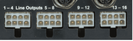
Line Level Outputs
These connectors provide unbalanced line-level analog audio outputs that are designed to feed external amplifiers or audio processing equipment.
Connector Information
| Speaker Connector | |
|---|---|
| Connector Type | 2x4 Molex Mini-Fit Jr. |
| Mating Plug | Molex 0039012080 |
| Mating Pins | Molex 0039000073 |
| Recommended Wire | 18 AWG Stranded |
Pinouts
Plug pinout (Wire-Side View)
| Line Outputs 1-4 | Line Outputs 5-8 | |||
|---|---|---|---|---|
| Line Output 1 | 1 | Line Output 5 | 1 | |
| Shield | 5 | Shield | 5 | |
| Line Output 2 | 2 | Line Output 6 | 2 | |
| Shield | 6 | Shield | 6 | |
| Line Output 3 | 3 | Line Output 7 | 3 | |
| Shield | 7 | Shield | 7 | |
| Line Output 4 | 4 | Line Output 8 | 4 | |
| Shield | 8 | Shield | 8 |
| Line Outputs 9-12 | Line Outputs 13-16 | |||
|---|---|---|---|---|
| Line Output 9 | 1 | Line Output 13 | 1 | |
| Shield | 5 | Shield | 5 | |
| Line Output 10 | 2 | Line Output 14 | 2 | |
| Shield | 6 | Shield | 6 | |
| Line Output 11 | 3 | Line Output 15 | 3 | |
| Shield | 7 | Shield | 7 | |
| Line Output 12 | 4 | Line Output 16 | 4 | |
| Shield | 8 | Shield | 8 |
Analog Voltage Input
This input can be used to monitor analog voltage levels between 0-10V. Example applications include monitoring a secondary power rail (i.e. 48VDC power rail for external amplifiers).

Connector Information
| Power Connector | |
|---|---|
| Connector Type | 2x4 Molex Mini-Fit Jr. |
| Mating Plug | Molex 0039012040 |
| Mating Pins | Molex 0039000073 |
| Recommended Wire | 18 AWG Stranded |
Pinouts
Plug pinout (Wire-Side View)
| Power | |
|---|---|
| Analog In (+) | 1 |
| Analog In (-) | 2 |
| Analog In (+) | 3 |
| Analog In (-) | 4 |
NOTE: When monitoring voltages higher than 10V, a voltage-divider circuit can be used to scale down the input to the 0-10V range.