Hardware Information
Overview
The V16X has an assortment of dedicated hardware for the purpose of configuration, status monitoring, and interfacing to other hardware. This section covers these features in more detail.
Display and Navigation
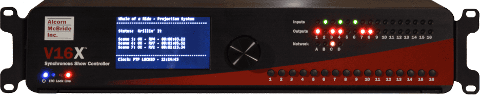
The front panel of V16X features a 12-line by 43-character TFT status display.

This display is primarily used to share application-specific information (i.e. “Preshow – Running - 01:02:03.00”) from the show control script. However, this display also offers a full menu system that can be accessed by pushing the navigation wheel adjacent to the display.
To access the menu system, simply press in the navigation wheel. The wheel can then be rotated and pressed to browse the menu system, select items, and change settings.
Below, you will find a description of the menu items that are available from this interface.
Main Menu
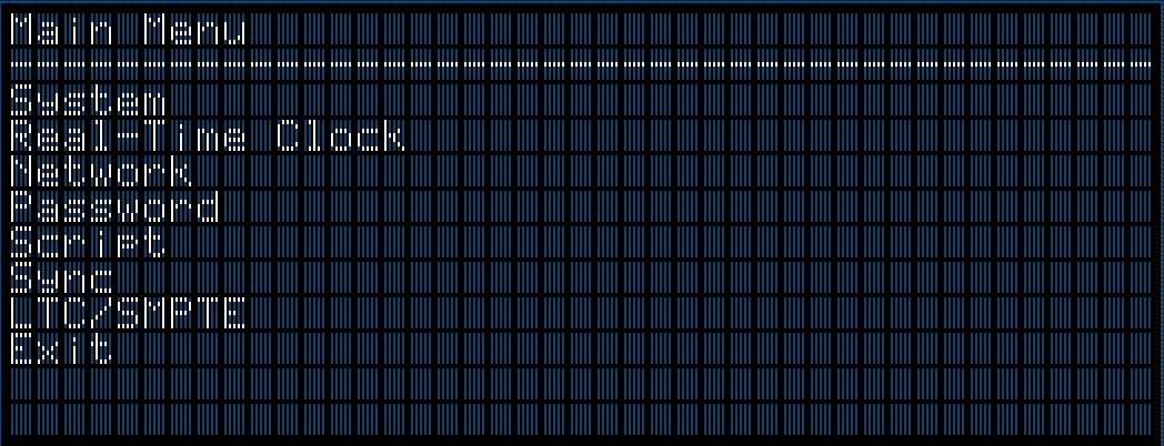
This menu provides access to the following sub-menus:
-
System -- Configure and monitor generic system status
-
Real-Time Clock -- Configure and monitor real-time clock
-
Network -- Configure network interface
-
Password -- Configure front-panel lockout password
-
Script -- Monitor show control performance and script status
-
Sync -- Monitor sync system status
-
LTC/SMPTE -- Monitor the SMPTE LTC status
-
Exit -- Exit the menu
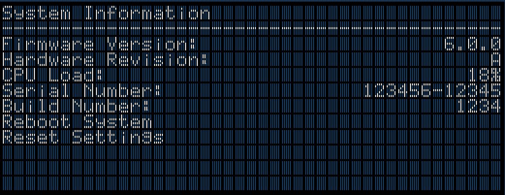
System Menu
-
Firmware Version -- Firmware version
-
Hardware Revision -- Revision of PCB hardware
-
Percent of Frame Used by Process -- Percent of frame time used by the show control script
-
Serial Number -- Chassis serial number
-
Uptime -- Elapsed time since start of show control script
-
Build Number -- Build revision of firmware
-
Reboot System -- Reboot controller and re-launch script
-
Reset Settings -- Reset all configuration data (i.e. network, device name, etc.) to factory defaults
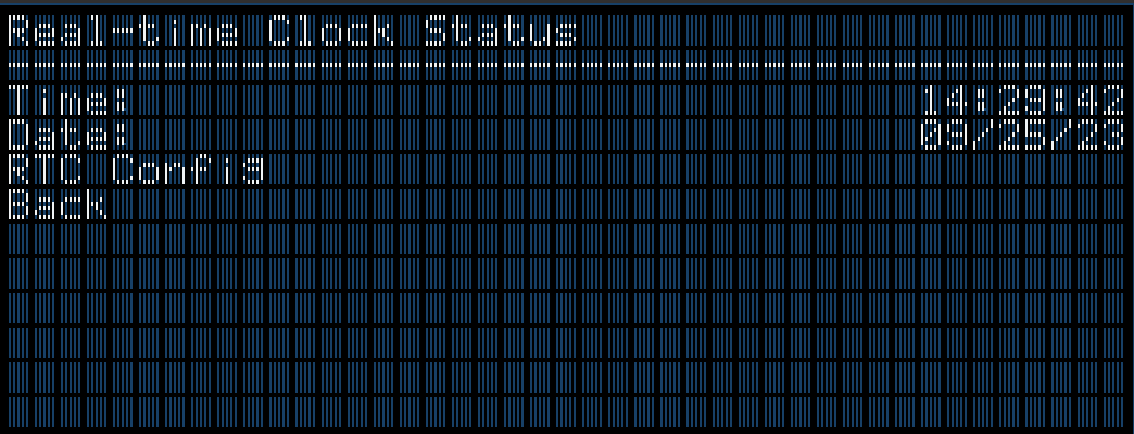
Clock Menu
-
Time -- Current system clock time
-
Date -- Current system clock date
-
RTC Config -- Used to set system clock time and date
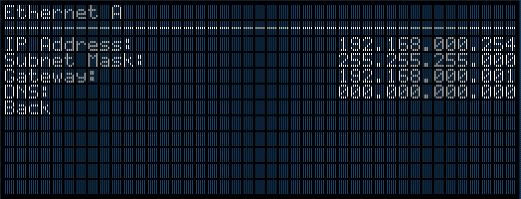
Network Menu
-
IP Address -- View/Configure IP address
-
Subnet Mask -- View/Configure subnet mask
-
Gateway -- View/Configure gateway IP address
-
DNS -- View/Configure DNS address
Password Menu

-
Password Protect Front Panel -- Enable/Disable Password Protection
-
Set Password -- Set/Modify front panel password
Script Menu

-
Script Filename -- Currently active show control script
-
Script Edit Date -- Edit date of active show control script
-
Reload Script -- Selecting this reloads and restarts the show control script
-
Device Name -- Assigned text name of the V16X
-
Device ID -- Assigned ID number of the V16X
-
Device Nickname -- Optional text nickname of the V16X
-
View Watches -- View watch list that is generated within the WinScript project
Sync Menu

-
Sync Source -- The configured sync source
-
Frame Rate -- Master frame rate of V16X
-
PTP Master -- Displays 'Yes' if V16X is operating as a PTP Master
-
NTP Master Address -- Show the NTP Server Address if V16X is operating as NTP Server
-
Genlock Out -- State of Genlock Output
-
Status -- Current state of V16X with configured Sync Source
-
Master Offset -- Accuracy of synchronized clocks
-
Last Update -- Time that has passed since last sync update
-
PTP Info -- Detailed status of PTP synchronization system
SMPTE/LTC Menu

-
Status -- Generate/Read, Current LTC value, framerate, and active status
-
Start SMPTE -- Enables the SMPTE interface to either Generate or Read based on configuration
Indicator LEDs
The front-panel of a V16X has a full set of indicator LEDs to provide an overall status of different features of the device.
Status
The status indicator LEDs are located in the lower left corner of the front-panel.

- Power - ON whenever power is applied to the unit and the power switch is on
- LTC - ON whenever SMPTE LTC is being actively generated or read
- Lock - ON whenever the sync system is locked to the configured sync source
- Live - ON whenever WinScript Live is connected to the unit
Network
The network indicator LEDs are located in the top right section of the front-panel.

These indicators display both network link and activity for all of the Network ports.
| LED State | Description |
|---|---|
| OFF | No Network Link |
| SOLID GREEN | Network link active – No network activity detected |
| BLINKING ORANGE | Network link active – Network activity detected |
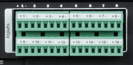
Inputs
The input indicator LEDs are located in the top right section of the front-panel.

These are digital inputs that can be used to trigger show control events. These inputs can be configured via software to accept contact-closure or voltage triggers (5-24VDC).
The table below defines the behavior of the indicator LEDs:
| LED State | Description |
|---|---|
| OFF | Inactive – No contact closure detected or voltage input is <9VDC |
| GREEN | Active – Contact closure detected or voltage input is 9-24VDC |
Outputs
The output indicator LEDs are located in the top right section of the front-panel.

These are dry-contact relay outputs that are rated to 900mA and protected with inline self-healing polymer fuses. These relays are normally open (NO) and both relay contacts (COMMON = C, and NORMALLY OPEN = NO) are accessible for each output.
The table below defines the behavior of the indicator LEDs:
| LED State | Description |
|---|---|
| OFF | Inactive – Relay contact is OPEN |
| RED | Active – Relay contact is CLOSED |
Buttons
The front panel buttons can be configured by WinScript Live software to trigger
show control. Panel space is available above these buttons to allow for labels to
be installed.

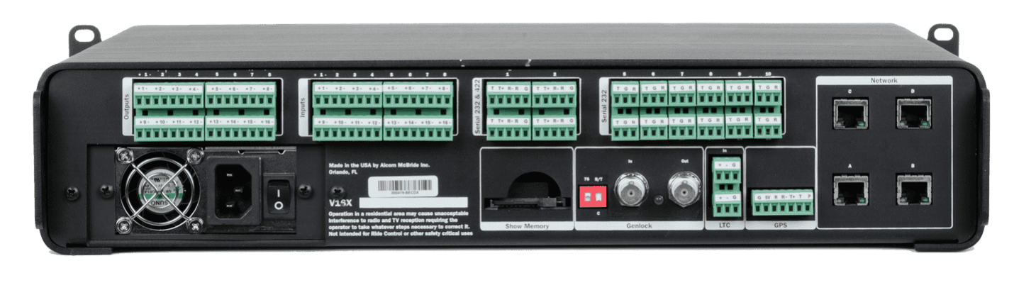
Connectors
Power Input - V16X
This connector is used to supply the standard V16X with power. This is a universal power supply that supports 110-240VAC at a frequency between 50-60Hz. This connector uses a standard IEC320 C14 socket, which can be used with an IEC320 C13 cable that is suitable for your region.

A power switch is located to the right of the power input, and can be used to power the unit ON or OFF.
An IEC Type B power cord is included with the V16X.
Connector Information
| AC Power Connector | |
|---|---|
| Connector Type | IEC320 C14 |
| Mating Plug | IEC320 C13 |
Power Input - V16X-DC
This connector is used to supply the DC-powered version of the V16X with power. This input is designed to accept anything between 18-36VDC with a maximum current of 3A. For added protection, a serviceable 3A automotive ATO/ATC blade fuse is pre-installed.
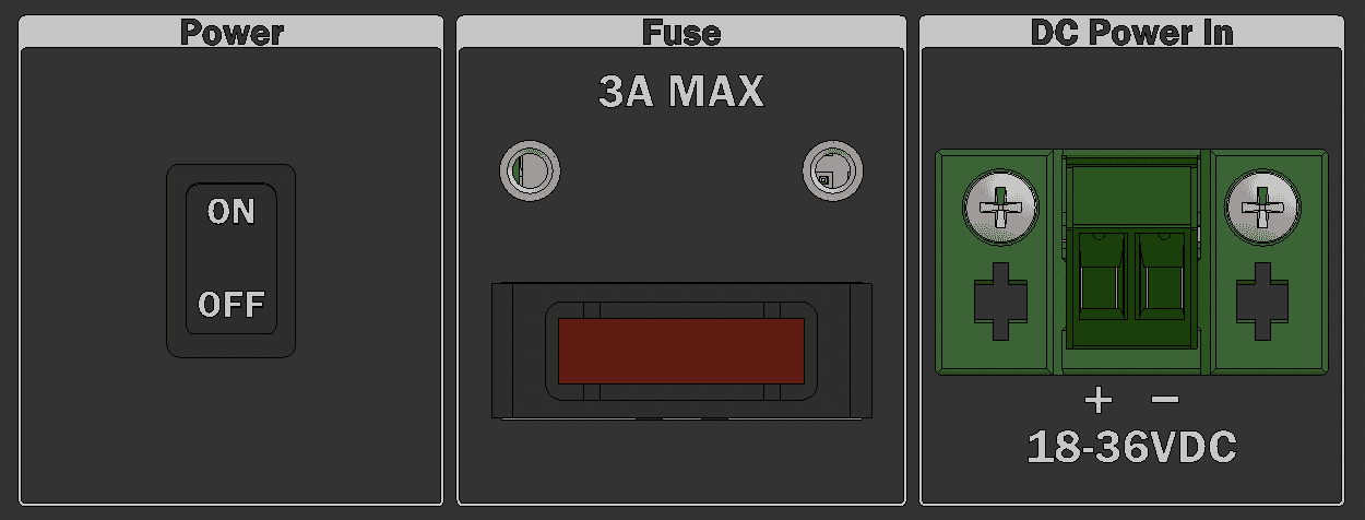
A power switch is located to the left of the 3A fuse and power input, and can be used to power the unit ON or OFF.
Connector Information
| DC Power Connector | |
|---|---|
| Connector Type | Phoenix 0707248 |
| Mating Plug | Phoenix 1757019 |
| Fuse | Littelfuse 166.7000.4302 |
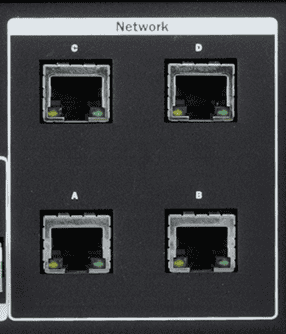
Network Ports
These are standard RJ45 Ethernet connectors that support 10/100/1000BT networks. They provide access to 4 isolated networks that can be used by the V16X to control and monitor devices that are connected to the networks. They are also used by a computer running our WinScript Live software to connect to the V16X to configure, program, and monitor the unit.
The network ports are isolated from each other. Network traffic does not flow between them.
Connector Information
| Network Connector | |
|---|---|
| Connector Type | RJ45 Female |
| Mating Plug | RJ45 Male |
Some portions of the network interface, such as FTP access, are protected with a configurable username and password. By default, these credentials are configured to:
| Default FTP Credentials | |
|---|---|
| User Name | admin |
| Password | password |
NOTE: Only network ports A and B can be used for PTP network synchronization.
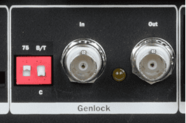
Genlock
These BNC connectors are used to connect external devices to the V16X genlock interface. When configured to lock to an external video sync source, the V16X will expect to see a Tri-level, Blackburst, or Composite Sync input on the 'IN' connector.
Regardless of the source sync reference, the V16X will always output a Composite Sync genlock signal on the 'OUT' connector. This allows external genlock devices like cameras, video servers, show controllers, etc. to lock and synchronize directly to the A/V clocks generated within V16X.
A yellow LED illuminates when the V16X has successfully genlocked to an incoming sync source. DIP switches allow the user to configure termination and video genlock type for the genlock input.
Connector Information
| Sync Connectors | |
|---|---|
| Connector Type | BNC Female |
| Mating Plug | BNC Male |
DIP Switch Information
| Termination Switch | |
|---|---|
| ON (UP) | 75 Ohm Termination |
| OFF (DOWN) | No Termination |
| Sync Type Switch | |
|---|---|
| ON (UP) | Blackburst/Tri-level |
| OFF (DOWN) | C-Sync |
Digital Inputs
The V16X is equipped with 16 discrete digital inputs that can be used as
show control triggers within your V16X script. Each input has two contacts
and can be software-configured within the WinScript Live project for two
modes of operation; contact closure or voltage (5-24VDC).
Mating plugs for these connectors ship pre-installed and labeled with the V16X.
Connector Information
| Input Connector | |
|---|---|
| Connector Type | Phoenix 1843130 |
| Mating Plug | Phoenix 5447926 |
| Recommeded Wire | 18 AWG Stranded |
Pinouts Inputs 1-8 are located on the top row connectors, and inputs 9-16 are located on the bottom row.

| Inputs (Top) | Inputs (Bottom) | |||
|---|---|---|---|---|
| Input 1 (+) | T1 | Input 9 (+) | B1 | |
| Input 1 (-) | T2 | Input 9 (-) | B2 | |
| Input 2 (+) | T3 | Input 10 (+) | B3 | |
| Input 2 (-) | T4 | Input 10 (-) | B4 | |
| Input 3 (+) | T5 | Input 11 (+) | B5 | |
| Input 3 (-) | T6 | Input 11 (-) | B6 | |
| Input 4 (+) | T7 | Input 12 (+) | B7 | |
| Input 4 (-) | T8 | Input 12 (-) | B8 | |
| Input 5 (+) | T9 | Input 13 (+) | B9 | |
| Input 5 (-) | T10 | Input 13 (-) | B10 | |
| Input 6 (+) | T11 | Input 14 (+) | B11 | |
| Input 6 (-) | T12 | Input 14 (-) | B12 | |
| Input 7 (+) | T13 | Input 15 (+) | B13 | |
| Input 7 (-) | T14 | Input 15 (-) | B14 | |
| Input 8 (+) | T15 | Input 16 (+) | B15 | |
| Input 8 (-) | T16 | Input 16 (-) | B16 |
Digital Outputs
The V16X is equipped with 16 discrete dry-contact relay outputs that are rated to 900mA and protected with inline self-healing polymer fuses. These relays are normally open (NO) and both relay contacts (COMMON = C, and NORMALLY OPEN = NO) are accessible for each output.
Mating plugs for these connectors ship pre-installed and labeled with the V16X.

Connector Information
| Input Connector | |
|---|---|
| Connector Type | Phoenix 1843130 |
| Mating Plug | Phoenix 5447926 |
| Recommeded Wire | 18 AWG Stranded |
Pinouts Outputs 1-8 are located on the top row connectors, and outputs 9-16 are located on the bottom row.

| Outputs (Top) | Outputs (Bottom) | |||
|---|---|---|---|---|
| Output 1 (+) | T1 | Output 9 (+) | B1 | |
| Output 1 (-) | T2 | Output 9 (-) | B2 | |
| Output 2 (+) | T3 | Output 10 (+) | B3 | |
| Output 2 (-) | T4 | Output 10 (-) | B4 | |
| Output 3 (+) | T5 | Output 11 (+) | B5 | |
| Output 3 (-) | T6 | Output 11 (-) | B6 | |
| Output 4 (+) | T7 | Output 12 (+) | B7 | |
| Output 4 (-) | T8 | Output 12 (-) | B8 | |
| Output 5 (+) | T9 | Output 13 (+) | B9 | |
| Output 5 (-) | T10 | Output 13 (-) | B10 | |
| Output 6 (+) | T11 | Output 14 (+) | B11 | |
| Output 6 (-) | T12 | Output 14 (-) | B12 | |
| Output 7 (+) | T13 | Output 15 (+) | B13 | |
| Output 7 (-) | T14 | Output 15 (-) | B14 | |
| Output 8 (+) | T15 | Output 16 (+) | B15 | |
| Output 8 (-) | T16 | Output 16 (-) | B16 |
Serial Ports
The V16X has a total of 16 serial ports that can be used to control devices.
Ports 1-4 can be configured to operate in either RS422 or RS232 mode, and
ports 5-16 operate in RS232 mode. Port 1 can also be configured to output
DMX512 for basic lighting control applications.
Mating plugs for these connectors ship pre-installed and labeled with the V16X.

Connector Information
| Serial Connectors (1-4) | |
|---|---|
| Connector Type | Phoenix 1843101 |
| Mating Plug | Phoenix 5447890 |
| Recommended Wire | 18 AWG Stranded |
| Serial Connectors (5-16) | |
|---|---|
| Connector Type | Phoenix 1843088 |
| Mating Plug | Phoenix 5447874 |
| Recommended Wire | 18 AWG Stranded |
Pinouts
| Serial Port 1 | |
|---|---|
| RS232 TX | 1 |
| RS422 TX(-) | 1 |
| DMX OUT (-) | 1 |
| RS422 TX (+) | 2 |
| DMX OUT (+) | 2 |
| RS422 RX (-) | 3 |
| RS232 RX | 4 |
| RS422 RX (+) | 4 |
| GND | 5 |
| Serial Ports 2-4 | |
|---|---|
| RS232 TX | 1 |
| RS422 TX(-) | 1 |
| RS422 TX (+) | 2 |
| RS422 RX (-) | 3 |
| RS232 RX | 4 |
| RS422 RX (+) | 4 |
| GND | 5 |
| Serial Ports 5-16 | |
|---|---|
| RS232 TX | 1 |
| GND | 2 |
| RS232 RX | 3 |
GPS Port
This port functions as a dedicated GPS interface (including PPS input) to provide highly accurate clock synchronization. It can function in both RS232 and RS422 modes and is configured via software.
A mating plug for this connector ships pre-installed and labeled with the V16X.

Connector Information
| GPS | |
|---|---|
| Connector Type | Phoenix 1803329 |
| Mating Plug | Phoenix 5447913 |
| Recommended Wire | 18 AWG Stranded |
Pinout
| GPS Port | |
|---|---|
| GND | 1 |
| GPS Power (+5VDC) | 2 |
| RS232 RX | 3 |
| RS422 RX (+) | 3 |
| RS422 RX (-) | 4 |
| RS422 TX (+) | 5 |
| RS232 TX | 6 |
| RS422 TX(-) | 6 |
| GPS PPS | 7 |
NOTE: The GPS Power output supplies +5VDC and has an inline self-healing polymer fuse rated for 200mA.
NOTE: The GPS PPS input is designed to accept a TTL-level (5V) pulse at a frequency of 1HZ.
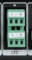
SMPTE LTC
These 3-pin terminal-style connectors provide access to the SMPTE Timecode (LTC) input and output.
Mating plugs for these connectors ship pre-installed with the V16X.
Connector Information
| SMPTE LTC Connector | |
|---|---|
| Connector Type | Phoenix 1843088 |
| Mating Plug | Phoenix 5447874 |
| Recommended Wire | 18 AWG Stranded |
Pinouts
The LTC Input is located on the top row, and the LTC Output is located on the bottom row.
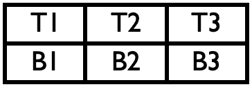
| LTC IN | LTC OUT | |||
|---|---|---|---|---|
| LTC IN (+) | T1 | LTC OUT (+) | B1 | |
| LTC IN (-) | T2 | LTC OUT (-) | B2 | |
| LTC IN (SHIELD) | T3 | LTC OUT (SHIELD) | B3 |