Script Configuration
When you start a new Script, the first dialog you see will be the Script Configuration dialog. You can access this dialog at any time by selecting Configuration->Script from the WinScript Live menu bar.
This dialog is the home of all of your script settings, including product type, BinloopX module types, clock settings, timezone, and more. The available sections depend on the type of device configured in the General section, so start there!
General
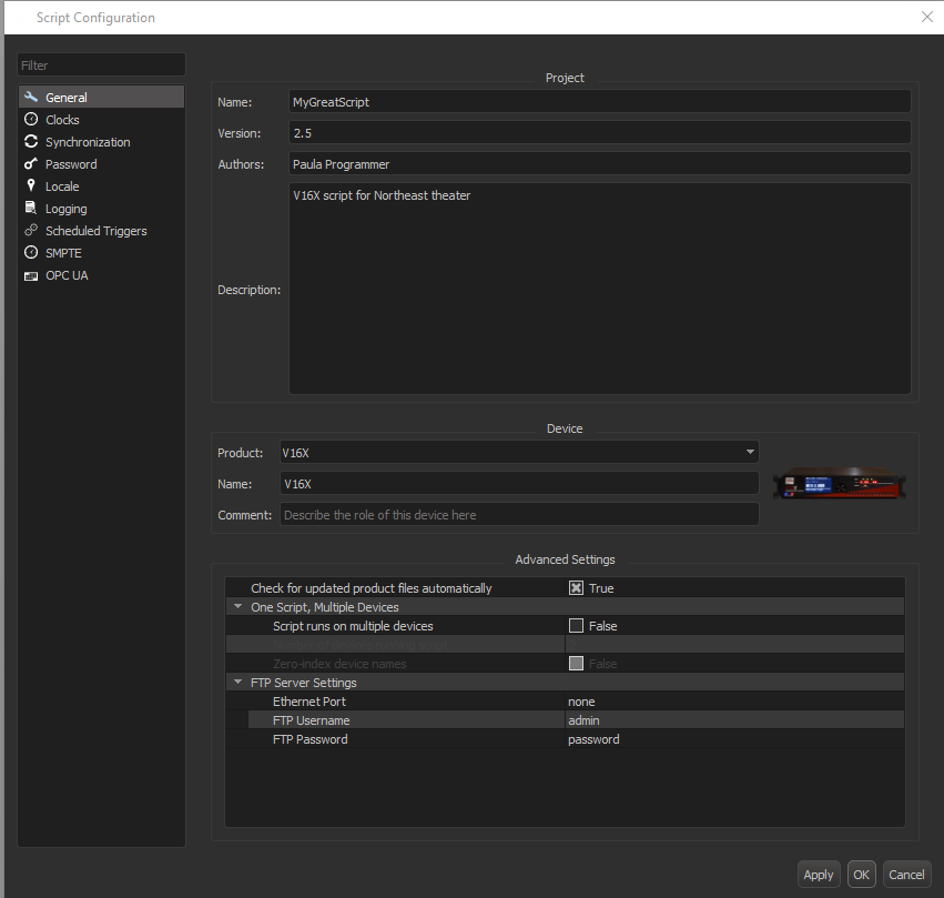
Project Section
The Name, Version, Authors, and Description fields are stored in the script file for reference. They have no functional effect on the script.
Device Section
The Product dropdown is the first thing that you should set when creating a new script. This tells WinScript Live which device you are creating a script for, allowing script resources to populate appropriately.
The Name field is used as the primary device name in your script. The device name specified here must match the device name assigned to the hardware before your script can be run. This can be changed at any time.
The Comment field is for your own note-keeping, and has no functional effect on the script.
Advanced Settings Section
This section holds miscellaneous script settings, including FTP, product file updates, and the ability to configure a script to run on multiple devices, for fleet applications.
Modules (BinloopX Only)
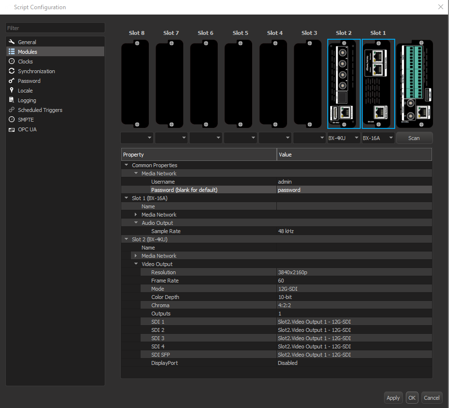
When creating a script for BinloopX, this configuration page allows you to specify which modules are installed in the BinloopX, and configure them as needed.
Modules types can be specified manually using the dropdown menus, or click Scan to connect to a BinloopX on your network and use that module layout.
Once you've configured your module types, you can configure module configuration below.
BX-16A Config Options
Name The module name will be displayed on the module display located on the front of the BinloopX.
Media Network These properties configure the Media Network ethernet port on the back of the BX-16A module.
Audio Output/Sample Rate This property sets the sample rate that the BX-16A module plays audio at. It should match your audio content. If this setting differs from the sample rate of your audio network, the module will automatically convert between the two sample rates.
BX-4KU Config Options
Name The module name will be displayed on the module display located on the front of the BinloopX.
Media Network These properties configure the Media Network ethernet port on the back of the BX-4KU module. This port should be used when faster media transfer speeds are desired.
Resolution The output resolution of the BX-4KU module. When this is 2K or lower resolution, there are 4 independent video outputs (imagine 4 separate players, each with stop/play/pause control). For 2160p or higher resolution, there is a single video output. If your media content stored on the BX-4KU does not match the output resolution, it will be scaled to match.
Frame Rate The output frame rate of the BX-4KU module. This determines the rate at which the image sequence plays. It's important to ensure that this framerate matches the frame rate at which the content was rendered for content to play correctly.
Mode This option determines the active video outputs on the BX-4KU, you can choose between various SDI modes and DisplayPort.
The available SDI modes depend on the chosen resolution and framerate. For instance, 4K60 output has the option of 12G SDI or Quad-link 3G SDI modes.
SDI and DisplayPort modes can not be active at the same time.
Color Depth For DisplayPort output modes, you can choose between 8-bit or 10-bit output. SDI is always 10-bit. If your media color depth does not match the output color depth, it will be automatically converted.
Chroma For DisplayPort output modes, you can choose between 4:2:2 and 4:4:4 output chroma. SDI is always 4:2:2 chroma. If your media chroma does not match the output chroma, it will be automatically converted.
Colorspace Choose between Rec.709 and Rec.2020 colorspace output. Media should be encoded with the same colorspace as this setting for color accuracy.
SDI 1/2/3/4/SFP These fields show you what signal is on each of the physical SDI connectors on the BX-4KU, and for output resolutions that allow multiple video outputs (like 1080p), these fields allow you to choose which output is assigned to which physical SDI connector.
By default, Output 1 is assigned to SDI 1 and so on, but you may mix these around or have the same video output on multiple SDI outputs if you'd like.
If these fields show "Disabled", you have chosen a DisplayPort output mode and SDI is not active.
The SDI SFP output is always a copy of the Copper SDI 1 output.
DisplayPort This field shows which Video Output is assigned to the DisplayPort connector. If this shows "Disabled", you have chosen an SDI output mode and DisplayPort is not active.
Clocks
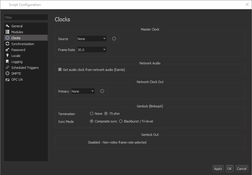
Master Clock
This section allows you to configure your device to lock to the sync reference of your choice, and specifies the frame rate that the main system show control clock runs at. See the Sync Core section for more information on clock types.
If your application does not require the use of an external reference clock, you can leave this selection at its default value of None. In this mode, the product will generate its own clocks internally.
Advanced Clock Source Settings
If using NTP as a clock source, clicking the gear icon next to the source dropdown box will allow you to set the NTP Server Address, as well as the Min Poll Rate and the Max Poll Rate.
These NTP polling times define the minimum and maximum amount of time in between packets sent to the NTP server. These polling times can be set to a variety of times between 1 second and 64 seconds. The default minimum polling time is 4 seconds, and the default maximum polling time is 8 seconds.
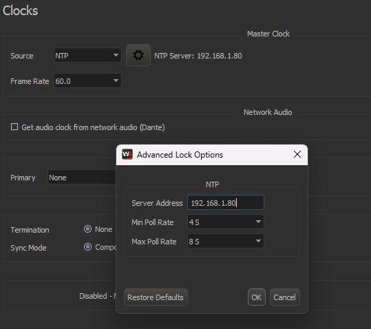
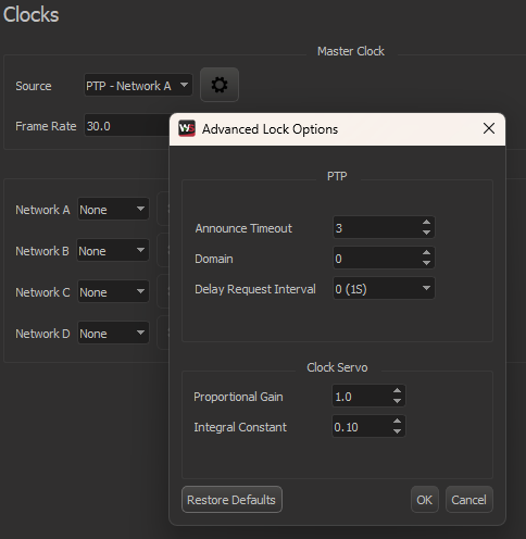
If using PTP as a clock source, clicking the gear icon next to the source dropdown box will allow you to configure the advanced settings for PTP.
The PTP Announce Timeout defines the number of intervals the controller will wait without receiving a PTP announcement before a timeout occurs. The default is 3 (8 seconds).
The PTP Domain setting allows you to isolate the controller from multiple Grandmaster Clocks across multiple networks. The default domain is 0.
The PTP Delay Request Interval is the minimum permitted mean time interval between Delay_Req messages. A shorter interval makes the controller react faster to the changes in the path delay. It's specified as a power of two in seconds. The default is 0 (1 second).
The Clock Servo settings let you set the PTP Proportional Gain and the PTP Integral Constant that the controller will use when locking to the PTP master. These clock servo settings can have drastic impact on PTP performance and clock stability, so it is not recommended to change these values.
Network Audio
Only available on devices with a network audio output, this option specifies whether audio playback uses the network audio (Dante/AES67) clocks, or the SyncCore clocks for audio playback. If you are sync'ing multiple devices using SyncCore, it is recommended that you leave this box unchecked.
Network Clock Out
SyncCore is not only capable of locking to an external sync reference, it can also distribute PTP or NTP as well. For products with multiple network ports, you can choose which protocol (if any) is active on each port. All SyncCore devices distribute PTPv2.
On devices with multiple PTP capable network ports (like V16X), it's possible to make the device act as a boundary clock by choosing PTP and the Clock Source and also choosing PTP as the Network Clock Out on a different port.
It is also possible for SyncCore-enabled devices to lock to an external reference and simultaneously distribute different type of reference. A common example of this would be configuring a V16X to lock to an external PTP Master (i.e. Ride Control PLC). This V16X may then need to synchronize precisely with RidePlayerX units over a wireless network which does not support PTP distribution. To overcome the limitations of the wireless network, the V16X could be configured to re-distribute the sync reference as an NTP Server. You could then configure the RidePlayerX units to lock to the V16X via NTP.
Advanced PTP Distribution Settings
If distributing a clock out over the network using PTP, clicking the gear icon next to the source dropdown box will allow you to configure the advanced settings for PTP.
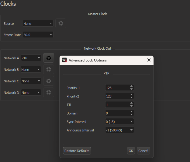
Priority 1/Priority 2 is used in the best master selection algorithm, lower values take precedence. Must be in the range 0 to 255. The default is 128.
TTL specifies the Time to live value for IPv4 multicast messages and the hop limit for IPv6 multicast messages. This option is only relevant with the IPv4 and IPv6 UDP transports. The default is 1 to restrict the messages sent by the controller to the same subnet.
Domain allows you to isolate the controller from multiple Grandmaster Clocks across multiple networks. The default domain is 0.
Sync Interval is the mean time interval between Sync messages. A shorter interval may improve accuracy of the local clock. It's specified as a power of two in seconds. The default is 0 (1 second).
Announcement Interval is the mean time interval between Announce messages. A shorter interval makes the controller react faster to the changes in the master-slave hierarchy. The interval should be the same in the whole domain. It's specified as a power of two in seconds. The default is -1 (500 milliseconds).
Genlock Config
Only available on BinloopX, this section lets you configure the termination and output mode of the Genlock output. Termination and output mode are configured via dip-switch on other SyncCore products.
Genlock Out
This section indicates the configured output framerate of the Genlock Output. Genlock is distributed automatically based upon the Frame Rate you have selected for the Master Clock. Keep in mind that not all frame rates are compatible with the video standards supported by the Genlock output circuit. Supported rates include 59.94, 50, 29.97, and 25 fps.
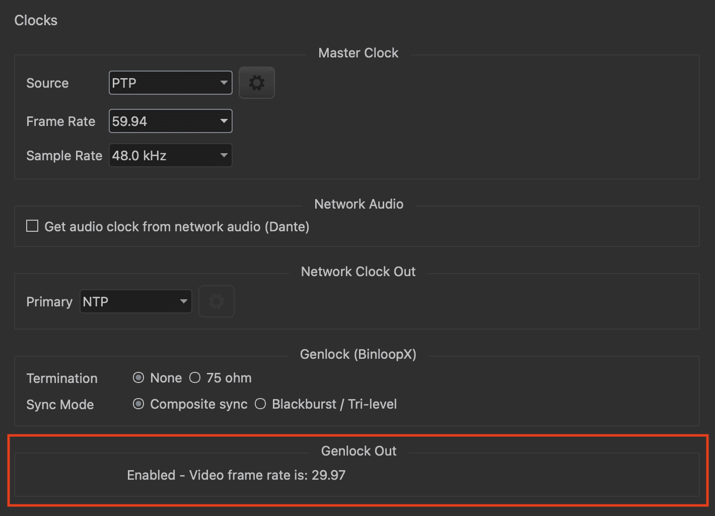
If you choose any other frame rate, WinScript Live will indicate that the Genlock output is disabled:

Synchronization
This section hold a single option, but an important one - the Pre-Roll Duration. Learn more in the pre-roll section of this guide.
Password
This section allows the user to set a script password. Setting a script password causes WinScript Live to prompt for the password before opening the script.
Locale
This section allows the user to set timezone, daylight savings time, and location of the device. Location settings, via latitude and longitude, are used to calculate the appropriate times of sunrise and sunset sequence triggers.
Logging
This section allows you to enable operational logs, and set the maximum size that the logs will take up on internal device storage. You can find more information on operation in the debugging section of this guide.
Scheduled Triggers
This section let's you configure the "Allowable Lag" of scheduled sequence triggers. Allowable lag is the maximum amount of time past a trigger time that a scheduled sequence trigger will still execute. Learn more in the Scheduled Sequence Triggers section of this guide.
SMPTE
This section configures the framerate of the SMPTE LTC reader and generator, if available on your device. You may also configure the LTC generator to start automatically on power-up.
OPC UA
This section allows you to enable and configure a OPC UA server interface. You can find more information on these options and how to use OPC UA in the OPC UA section of this guide.