Getting Started
This article will teach you how to begin using your AMIO and configure your IP address.
Connecting the Power Supply to the coupler
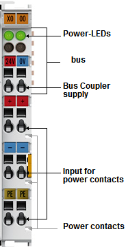
Connect 24V from the power supply to the coupler on the inputs marked "Bus coupler supply" and "Input for power contacts" as shown in Figure 1.
The power contacts run along the side of the module and are not visible when the input and output modules are added.
LEDs indicate the supply voltage status. The left LED indicates the presence of the 24V supply. The right LED indicates the presence of the supply to the power contacts.
Connecting and Disconnecting I/O Modules
Input/Output (I/O) modules can be arranged in any order. The coupler recognizes the terminals to which they are connected, and performs the assignment of the inputs and outputs automatically.
A total of 512 I/O modules may be connected to a single coupler. When using WinScript Live, a maximum of 255 modules may be used (total of 1020 I/O).
Each I/O module can be removed by pulling on the orange tabs on the side of the module.
Using Input Modules
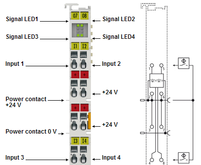
Each input module contains 4 inputs marked as "Input 1-4" as shown in Figure 2. The top and bottom 4 LEDs marked as "Signal LED1-4" indicate the status of the 4 inputs. The digital input terminals acquire the binary 24V control signals and retransmit their status to the coupler.
Four 24V connection points are provided marked as "+24 V".
"Power contacts 24V" and "Power contact 0V" run along the side of the left module (not visible when connected to other modules).
Input Modules are labeled as 1404 on the bottom of the module.
Using Output Modules
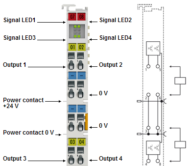
Each output module contains 4 outputs marked as "Output 1-4" as shown in Figure 3. The top and bottom 4 LEDs marked as "Signal LED1-4" indicate the status of the 4 outputs. The 4-channel terminals enable the direct connection of four 2-wire sensors.
Four ground connection points are provided marked as "0 V".
"Power contacts 24V" and "Power contact 0V" run along the side of the left module (not visible when connected to other modules).
Output modules are labeled as 2404 on the bottom of the module.
Controlling AMIO Using WinScript Live
WinScript Live is our program to configure Alcorn McBride Show Controllers (and more!)
To quickly connect AMIO to a show controller without changing IP addresses, connect to "Port B" of the show controller (usually IP address 192.168.0.253). Then, add the AMIO to the Devices screen in WinScript Live using IP address 192.168.0.254.
See AMIO with WinScript Live for more details.
Setting the IP Address
Configuring the IP address can be done via WinScript Live (easiest method for use with our Show Controllers), using a DHCP server, or using an "ARP" command.
If you are not using one of our show controllers (first of all, how dare you), the "ARP" method is usually the preferred method.
The default IP address is 192.168.0.254.
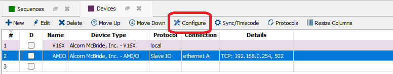
IP Address Configuration via WinScript Live
Address configuration can be done in the Devices window in WinScript Live. After adding an AMIO device, click Configure as shown in Figure 4.
Alternatively, click "Find Device" while in the "Add Device" wizard.
The wizard will appear to help find the AMIO or set the IP address on the AMIO. Follow the on-screen instructions.
For more details on the WinScript Live configuration dialogs, see AMIO with WinScript Live.
IP Address Configuration via ARP
An easy method of modifying the IP address is to set the address using the DOS window. It is, however, only possible to alter addresses within the same network class. The new IP address that has been set remains stored even after the coupler has been switched off.
The default IP address for the AMIO is 192.168.0.254, so make sure your PC is on the same network as the AMIO.
You must know the IP address of the AMIO before using this method.
Note
This requires administrative privileges on Windows.
Procedure
- Set DIP switches 9 and 10 to OFF. DIP switches 1-8 then no longer have any address function.
- Open a command line on your PC.
- Enter the command "ping
<OLD IP address>" to create an entry in the ARP table. - Read the table with the command "arp -a".
- Enter "arp -d
<OLD IP address>" to remove the Bus coupler from the table. - Use "arp -s
<NEW IP address><MAC-ID>" to make an entry manually. - With "ping -l 123
<NEW IP address>" the new IP address becomes valid. - A short flash from the ERROR LED at the moment of switching on indicates that the Bus coupler is being addressed by ARP, and that DIP switches 1-8 give no indication of the address that is set.
Note
When the IP address is changed, all the dynamic ARP entries should be cleared. To change the IP address, one ping with the length of 123 bytes is permitted (<ping -l IP Address>).
Example:
C:>ping 192.168.0.254
C:>arp -a
192.168.0.254 00-01-05-00-11-22
C:>arp -d 192.168.0.254
C:>arp -s 192.168.44.44 00-01-05-00-11-22
C:>ping -l 123 192.168.44.44
IP Address Configuration via DHCP Server
To set the address by means of a DHCP server, set DIP switch 9 to OFF (0) and DIP switch 10 to ON (1).
In this state, the DHCP service is switched on, and the coupler is assigned an IP address by the DHCP server.
For this purpose the DHCP server must know the coupler's MAC-ID and should assign the same IP address to this MAC-ID at every startup.
The TCP/IP Error LED flashes while the address is being allocated.