Hardware Information
Overview
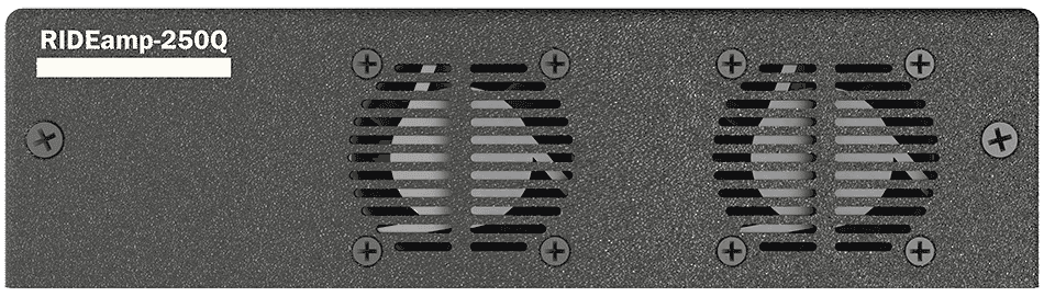
RideAmp-250Q has a variety of dedicated hardware for the purpose of configuration, status monitoring, and interfacing to other hardware. This section covers these features in more detail.
Indicator LEDs
The top panel of RideAmp has a full set of indicator LEDs to provide an overall status of different features of the device. This includes power, network, audio signal, and amplifier status. Read on for details on the functionality of each LED.

Power
The status indicator LEDs are located in the lower left corner of the front-panel.

| LED State | Description |
|---|---|
| OFF | No Power |
| BLUE | DC Power Applied - System OK |
| RED | DC Power Applied - System FAULT |
Network
These indicators display both network link and activity for all the Network Audio ethernet ports.

| LED State | Description |
|---|---|
| OFF | No Network Link |
| SOLID ORANGE | Network Link Active - No activity detected |
| BLINKING ORANGE | Network Link Active - Activity detected |
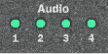
Audio
These indicators display the signal activity for all 4 audio outputs as well as the mute status.
| LED State | Description |
|---|---|
| OFF | No Audio Signal |
| GREEN | Active Audio Signal |
| RED | Audio Output is MUTED |
Status
These indicators display the operational status of each amplifier channel.

| LED State | Description |
|---|---|
| OFF | Amplifier OFF/INACTIVE |
| SOLID GREEN | Amplifier OK |
| PULSING ORANGE | Amplifier OK - Audio Clipping |
| SOLID ORANGE | Thermal Warning or Single Fan Failure |
| FLASHING ORANGE | Recorded Warning (Recovered) |
| SOLID RED | Amplifier Fault - Thermal, Overload Protect, Dual Fan Failure |
| FLASHING RED | Recorded Fault (Recovered) |
NOTE: The amplifier will attempt to auto-clear faults every 10 seconds. Note, hard mutes are engaged on thermal fault condition only.
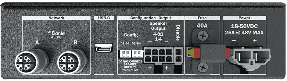
Connectors
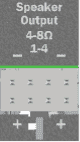
Speaker Outputs
This is where you connect speakers to the RideAmp. You can wire up to 4 discrete channels of 4-ohm speakers at up to 255W each (or 150W each at 8 ohms), or you can bridge (parallel) each channel pair to achieve up to 500W x 2 channels into 2 ohms (or 290W each at 4 ohms bridged).
NOTE: NEVER CONNECT ANY OF THE SPEAKER OUTPUTS TO GROUND. THE AMPLIFIER WILL IMMEDIATELY GO INTO AN OVERCURRENT FAULT CONDITION.
Connector Information
| Speaker Connector | |
|---|---|
| Connector Type | 2x4 Molex Mini-Fit Jr. |
| Mating Plug | Molex 0039012080 |
| Mating Pins | Molex 0039000185 |
| Recommended Wire | 16 AWG Stranded |
Pinouts
Plug pinout (Wire-Side View)

Non-Bridged Wiring
The following pinouts apply when speaker outputs are being used individually for up to 255W operation.

| Speakers (Non-Bridged) | |
|---|---|
| Speaker 1 (-) | 1 |
| Speaker 1 (+) | 5 |
| Speaker 2 (-) | 2 |
| Speaker 2 (+) | 6 |
| Speaker 3 (-) | 3 |
| Speaker 3 (+) | 7 |
| Speaker 4 (-) | 4 |
| Speaker 4 (+) | 8 |
Parallel Bridged Wiring
The following pinouts apply when speaker outputs are parallel bridged for up to 500W operation. Bridging is configured within the RideAmp Utilities application.

| Speakers (Parallel Bridged) | |
|---|---|
| Speaker 1/2 (-) | 1+2 |
| Speaker 1/2 (+) | 5+6 |
| Speaker 3/4 (-) | 3+4 |
| Speaker 3/4 (+) | 7+8 |
Amplifier Disable Input
The Disable Input is a discrete contact-closure input that will disable the amplifier when shorted. When left disconnected the amplifier defaults to Enabled.

Connector Information
| Amp Disable Connector | |
|---|---|
| Connector Type | 1x2 Molex Mini-Fit Jr. |
| Mating Plug | Molex 0039012025 |
| Mating Pins | Molex 0039000185 |
| Recommended Wire | 16 AWG Stranded |
Pinouts
Plug pinout (Wire-Side View)

A Contact closure between Pin 1 and Pin 2 will disable the amplifier. The current through the external contact is minimal, typically on the order of 10–20 mA.
Network
RideAmp provides a total of two M12 X-Coded network ports. These ports are devoted to a 4x0 (4 inputs, 0 outputs) network audio interface that supports the AES67 and Dante standards. When using Dante, these ports also pass back important status information via the network link to a RidePlayer for monitoring amplifier health.
Two connectors are provided for each of these network connections to allow multiple RideAmp units to be daisy-chained without the need for an external M12 Ethernet switch. These ports can also be configured for redundancy as part of the Dante capabilities.

Connector Information
| Network Connector | |
|---|---|
| Connector Type | M12 X-Code Female |
| Mating Plug | M12 X-Code Male |
Power
RideAmp can operate from any DC power source with a voltage between 18-50VDC. A single inline automotive blade fuse (40A/80V) is accessible on the RideAmp connector panel. Voltage levels are electronically monitored, and low voltage conditions can be reported back via the network audio connection to a RidePlayer. A shutdown voltage threshold can also be programmed, so that the amplifier is automatically disabled below a set minimum voltage.

Connector Information
| Power Connector | |
|---|---|
| Connector Type | 1x2 Molex Mini-Fit Sr. |
| Mating Plug | Molex 0428160212 |
| Mating Pins | Molex 428150032 (8AWG) |
| Molex 0428150012 (10-12AWG) | |
| Recommended Wire | 8 AWG for full-rated operation at maximum current draw |
| 10-12 AWG may be used for reduced-current applications |
Pinouts

| Power Connector | |
|---|---|
| DC Power (-) | 1 |
| DC Power (+) | 2 |
USB
RideAmp is equipped with a standard USB-C connector which is used to communicate with a PC laptop running the RideAmp Utility Application. This port can also be used to perform firmware updates when necessary.

Configuration Switches
These configuration switches can be used to apply different modes and actions, such as resetting factory defaults. DOWN is the ON position.

| D1 - Reset Defaults | |
|---|---|
| ON (DOWN) | Reset Factory Defaults |
| OFF (UP) | Normal Operation |
| D2 - Bootloader Mode | |
|---|---|
| ON (DOWN) | Force Bootloader Mode |
| OFF (UP) | Normal Operation |
| D3 - Unused | |
|---|---|
| ON (DOWN) | Normal Operation |
| OFF (UP) | Normal Operation |
| D4 - Unused | |
|---|---|
| ON (DOWN) | Normal Operation |
| OFF (UP) | Normal Operation |