Hardware Information
Overview
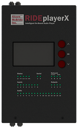
RidePlayer has quite an assortment of dedicated hardware for the purpose of configuration, status monitoring, and interfacing to other hardware. This section covers these features in more detail.
Display and Navigation
The top panel of RidePlayer features an 8-line by 42-character OLED status display. This display is primarily used to share application-specific information (i.e. “Location: Scene 2”) from the show control script. However, this display also offers a full menu system that can be accessed using the navigation buttons located adjacent to the display
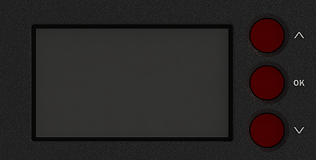
Below, you will find a description of the menu items that are available from this interface.
Main Menu
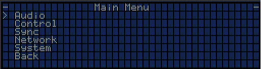
This menu provides access to the following sub-menus:
-
Audio -- Monitor and control audio interface
-
Control -- Monitor show control performance and script status
-
Sync -- Monitor sync system status
-
Network -- Configure network interface
-
System -- Configure and monitor generic system status
-
Exit -- Exit the menu
Audio Menu
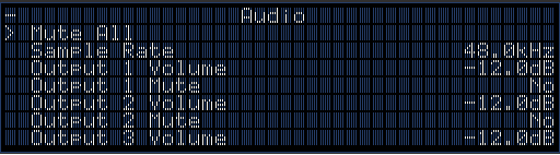
This menu provides access to the following sub-menus:
-
Mute All -- Mute/Unmute all audio outputs
-
Sample Rate -- View current audio sample rate (44.1KHz or 48.0KHz)
-
Output Volume -- Set volume level of individual output (-128dB->0dB)
-
Output Mute -- Mute/Unmute individual output
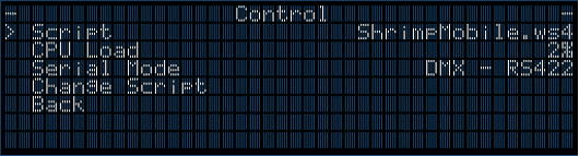
Control Menu
-
Script -- View currently active show control script
-
CPU Load -- View current load of show control processor
-
Serial Mode -- View mode of operation for multi-purpose serial port
-
Change Script -- Select a new active script file
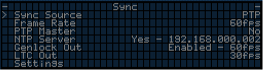
Sync Menu
-
Sync Source -- The configured sync source
-
Frame Rate -- Master frame rate of RidePlayer
-
PTP Master -- Displays 'Yes' if RidePlayer is operating as a PTP Master
-
NTP Server -- Show the NTP Server Address if RidePlayer is operating as NTP Server
-
Genlock Out -- State of Genlock Output
-
LTC Out -- View operating frame rate of SMPTE LTC interface
-
PTP Info -- View detailed information about PTP status
-
Sync Status -- Time that has passed since last sync update
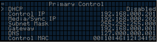
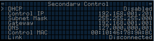
Network Menu
-
DHCP -- Enable/Disable DHCP network configuration
-
Control IP -- View/Configure Show Control IP address
-
Media/Sync IP -- Media/Sync IP address (Primary Only - Used for NTP/PTP sync and media file transfer)
-
Subnet Mask -- View/Configure subnet mask
-
Gateway -- View/Configure gateway IP address
-
DNS -- View/Configure DNS address
-
Control MAC -- View MAC address for Show Control Ethernet interface
-
Media/Sync MAC -- View MAC address for Media/Sync Ethernet interface
-
Link -- Current link status of network port
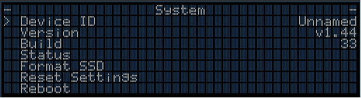
System Menu
-
Firmware Version -- Firmware version
-
Hardware Revision -- Revision of PCB hardware
-
Percent of Frame Used by Process -- Percent of frame time used by the show control script
-
Serial Number -- Chassis serial number
-- Uptime -- Elapsed time since start of show control script
-
Build Number -- Build revision of firmware
-
Reboot System -- Reboot controller and re-launch script
-
Reset Settings -- Reset all configuration data (i.e. network, device name, etc.) to factory defaults
Indicator LEDs
The top-panel of RidePlayerX has a full set of indicator LEDs to provide an overall status of different features of the device.
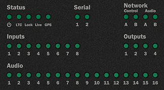
Status LEDs
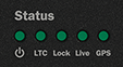
Power -- ON whenever power is applied to the unit and the power switch is on
LTC -- ON whenever SMPTE LTC is being actively generated or read
Lock -- ON whenever the sync system is locked to the configured sync source
Live -- ON whenever WinScript Live is connected to the unit
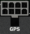
GPS -- ON whenever an active GPS receiver is connected
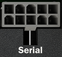
Serial

These indicators blink to indicate activity on either serial port.
Network
The network indicator LEDs are located in the top right section of the top-panel.

These indicators display both network link and activity for all of the Network ports.
| LED State | Description |
|---|---|
| OFF | No Network Link |
| SOLID ORANGE | Network link active – No network activity detected |
| BLINKING ORANGE | Network link active – Network activity detected |
Inputs
The input indicator LEDs are located in the middle left section of the top-panel.
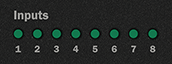
These are digital inputs that can be used to trigger show control events. These inputs can be configured via software to accept contact-closure or voltage triggers.
The table below defines the behavior of the indicator LEDs:
| LED State | Description |
|---|---|
| OFF | Inactive – No contact closure detected or voltage input is <9VDC |
| GREEN | Active – Contact closure detected or voltage input is 9-24VDC |
Outputs
The output indicator LEDs are located in the middle right section of the top-panel.

These are solid-state relay outputs that are rated to 400mA and protected with inline self-healing polymer fuses. These relays are normally open (NO) and both relay contacts (COMMON = C, and NORMALLY OPEN = NO) are accessible for each output.
The table below defines the behavior of the indicator LEDs:
| LED State | Description |
|---|---|
| OFF | Inactive – Relay contact is OPEN |
| GREEN | Active – Relay contact is CLOSED |
Audio
The Audio Status LEDs are located in the bottom section of the top-panel.
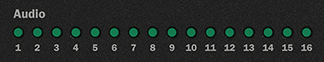
These indicators display the status of all 16 audio outputs. This includes playback activity and audio mute status.
| LED State | Description |
|---|---|
| OFF | No Audio Playback |
| GREEN | Audio playback in progress |
| RED | Audio output is MUTED |
Connectors
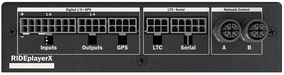
Network Control
These are standard M12 X-Coded Ethernet connectors, and are both used for show control, network synchronization, and media file management. These ports (A and B) are completely isolated from one another (no internal switches or bridging) and each have their own configurable IP address.

Connector Information
| Network Connector | |
|---|---|
| Connector Type | M12 X-Coded Female |
| Mating Plug | M12 X-Coded Male |
Some portions of the network interface, such as FTP access, are protected with a configurable username and password. By default, these credentials are configured to:
| Default FTP Credentials | |
|---|---|
| User Name | admin |
| Password | password |
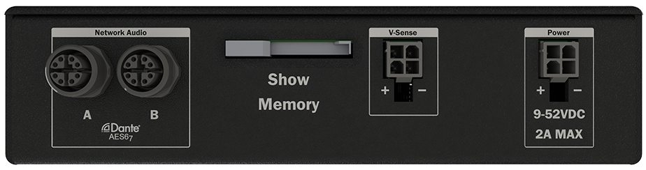
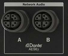
Network Audio
These are also standard M12 X-Coded Ethernet connectors. They provide access to the 16x16 network audio interface that supports the AES67 and Dante standards. There are two connectors (A and B) with an integrated internal switch to support daisy-chaining with network audio devices like RideAmps as well as support easy interfacing with a computer running Dante Controller without requiring any external switch hardware.
Once connected, this network audio interface can be configured using the Audinate Dante Controller software. This application provides the ability to configure IP settings, name outputs, create Dante/AES67 flows, and route transmitters to receivers. To learn more about how to configure the network audio interface, be sure to read the Network Audio section.
Connector Information
| Network Connector | |
|---|---|
| Connector Type | M12 X-Coded Female |
| Mating Plug | M12 X-Coded Male |
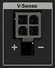
V-Sense Input
This input can be used to monitor analog voltage levels between 0-100VDC. This is intended to monitor a secondary power rail (i.e. 48VDC power rail for external amplifiers).
Connector Information
| V-Sense Connector | |
|---|---|
| Connector Type | 2x4 Molex Mini-Fit Jr. |
| Mating Plug | Molex 0039012040 |
| Mating Pins | Molex 0039000185 |
| Recommended Wire | 18 AWG Stranded |
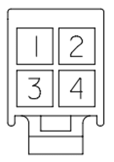
Pinouts
Plug pinout (Wire-Side View)
| V-Sense | |
|---|---|
| V-Sense (+) | 1 |
| GND | 2 |
| V-Sense (+) | 3 |
| GND | 4 |
Serial
This connector provides access to the Serial Control and DMX features. This includes two serial ports that can be configured to operate in either RS232 or RS422 modes. Both of these ports can be used for multi-purpose serial control, and Port 1 can be configured for DMX lighting control.
Connector Information
| Serial Connector | |
|---|---|
| Connector Type | 2x5 Molex Mini-Fit Jr. |
| Mating Plug | Molex 0039012100 |
| Mating Pins | Molex 0039000073 |
| Recommended Wire | 18 AWG Stranded |
Pinouts
Plug pinout (Wire-Side View)

| Serial Port 1 (RS-232) | |
|---|---|
| Serial RS232 TX | 1 |
| Serial RS232 RX | 7 |
| Ground | 3 |
| Serial Port 1 (RS-422) | |
|---|---|
| Serial RS422 TX(-) | 1 |
| Serial RS422 TX(+) | 2 |
| Serial RS422 RX(-) | 6 |
| Serial RS422 RX(+) | 7 |
| Ground | 3 |
| Serial Port 1 (DMX512) | |
|---|---|
| DMX Out(-) | 1 |
| DMX Out(+) | 2 |
| Ground | 3 |
| Serial Port 2 (RS-232) | |
|---|---|
| Serial RS232 TX | 4 |
| Serial RS232 RX | 10 |
| Ground | 8 |
| Serial Port 2 (RS-422) | |
|---|---|
| Serial RS422 TX(-) | 4 |
| Serial RS422 TX(+) | 5 |
| Serial RS422 RX(-) | 9 |
| Serial RS422 RX(+) | 10 |
| Ground | 8 |
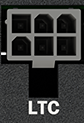
SMPTE LTC
This connector provides access to the SMPTE Timecode (LTC) input and output.
Connector Information
| SMPTE LTC Connector | |
|---|---|
| Connector Type | 2x3 Molex Mini-Fit Jr. |
| Mating Plug | Molex 0039012060 |
| Mating Pins | Molex 0039000073 |
| Recommended Wire | 18 AWG Stranded |
Pinouts
Plug pinout (Wire-Side View)
| LTC OUT | LTC IN | |||
|---|---|---|---|---|
| LTC OUT (+) | 4 | LTC IN (+) | 6 | |
| LTC OUT (-) | 1 | LTC IN (-) | 3 | |
| LTC OUT (SHIELD) | 5 | LTC IN (SHIELD) | 2 |
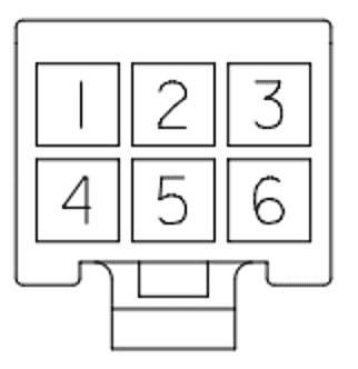
GPS
This connector offers a dedicated GPS input with support for the PPS signal.
This can be used for extremely precise synchronization of this product’s internal
system clock. It can also provide telemetry data like Latitude, Longitude,
Altitude, Velocity, etc. which can be access within the show control engine.
Connector Information
| GPS Connector | |
|---|---|
| Connector Type | 2x4 Molex Mini-Fit Jr. |
| Mating Plug | Molex 0039012080 |
| Mating Pins | Molex 0039000073 |
| Recommended Wire | 18 AWG Stranded |
Pinouts
Plug pinout (Wire-Side View)

| GPS Port (RS-232) | |
|---|---|
| GPS RS232 TX | 1 |
| GPS RS232 RX | 6 |
| GPS PPS | 3 |
| GPS Power (+5VDC) | 4 |
| Ground | 7 |
| Ground | 8 |
| GPS Port (RS-422) | |
|---|---|
| GPS RS422 TX(-) | 1 |
| GPS RS422 TX(+) | 2 |
| GPS RS422 RX(-) | 5 |
| GPS RS422 RX(+) | 6 |
| GPS PPS | 3 |
| GPS Power (+5VDC) | 4 |
| Ground | 7 |
| Ground | 8 |
NOTE: The GPS Power output supplies +5VDC and has an inline self-healing polymer fuse rated for 200mA.
Power Input
This connector is used to power the RidePlayerX. While this unit will operate with a power source between 9-52VDC, we recommend using a 12, 24, or 48VDC power supply with at least a 2A current rating.
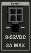
Connector Information
| Power Connector | |
|---|---|
| Connector Type | 2x4 Molex Mini-Fit Jr. |
| Mating Plug | Molex 0039012040 |
| Mating Pins | Molex 0039000185 |
| Recommended Wire | 18 AWG Stranded |
Pinouts
Plug pinout (Wire-Side View)
| Power | |
|---|---|
| PWR (+) | 1 |
| GND (-) | 2 |
| PWR (+) | 3 |
| GND (-) | 4 |
Note
Pins 1 and 3 (PWR (+) ) are connected internally, and pins 2 and 4 (GND (-) ) are connected internally. This allows RidePlayerX to use the same power connector as the original RidePlayer.
Regardless, RidePlayerX pulls so little power that only one pair of wires (1 for PWR and 1 for GND) should be required.
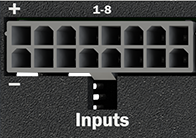
Digital Inputs
This connector provides access to 8 discrete digital inputs that can be used as show control triggers within your RidePlayerX script. Each input has two contacts and can be software-configured within the WinScript Live project for two modes of operation; contact closure or voltage.
Connector Information
| Input Connector | |
|---|---|
| Connector Type | 2x8 Molex Mini-Fit Jr. |
| Mating Plug | Molex 0039012160 |
| Mating Pins | Molex 0039000073 |
| Recommended Wire | 18 AWG Stranded |
Pinouts
Plug pinout (Wire-Side View)
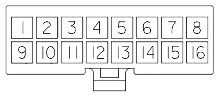
| Inputs 1-4 | Inputs 5-8 | |||
|---|---|---|---|---|
| Input 1 (+) | 1 | Input 5 (+) | 5 | |
| Input 1 (-) | 9 | Input 5 (-) | 13 | |
| Input 2 (+) | 2 | Input 6 (+) | 6 | |
| Input 2 (-) | 10 | Input 6 (-) | 14 | |
| Input 3 (+) | 3 | Input 7 (+) | 7 | |
| Input 3 (-) | 11 | Input 7 (-) | 15 | |
| Input 4 (+) | 4 | Input 8 (+) | 8 | |
| Input 4 (-) | 12 | Input 8 (-) | 16 |
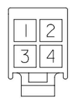
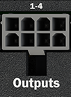
Digital Outputs
The RidePlayerX is equipped with 4 discrete solid-state relay outputs that are rated to 400mA and protected with inline self-healing polymer fuses. These relays are normally open (NO) and both relay contacts (COMMON = C, and NORMALLY OPEN = NO) are accessible for each output.
Connector Information
| Output Connector | |
|---|---|
| Connector Type | 2x4 Molex Mini-Fit Jr. |
| Mating Plug | Molex 0039012080 |
| Mating Pins | Molex 0039000073 |
| Recommended Wire | 18 AWG Stranded |
Pinouts
Plug pinout (Wire-Side View)
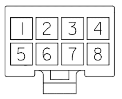
| Outputs | |
|---|---|
| Output 1 (A) | 1 |
| Output 1 (B) | 5 |
| Output 2 (A) | 2 |
| Output 2 (B) | 6 |
| Output 3 (A) | 3 |
| Output 3 (B) | 7 |
| Output 4 (A) | 4 |
| Output 4 (B) | 8 |