Hardware Information
Hardware Overview
VC12X
VC16K
Zone Status LEDs
| LED State | Description |
|---|---|
| Station ringing | |
| Ring Zone available | |
| Off | No Ring Zone assigned |
| Link active | |
| No sync / no Q-SYS Core detected | |
| Firmware update mode |
Note
These indicators can be overridden using the Breakaway feature of the V-Com plugin. This allows you to take manual control of the LED status using IO pins in Q-SYS Designer.
Note
On the V-Com VC16K, an indicator output is available for each zone select input.
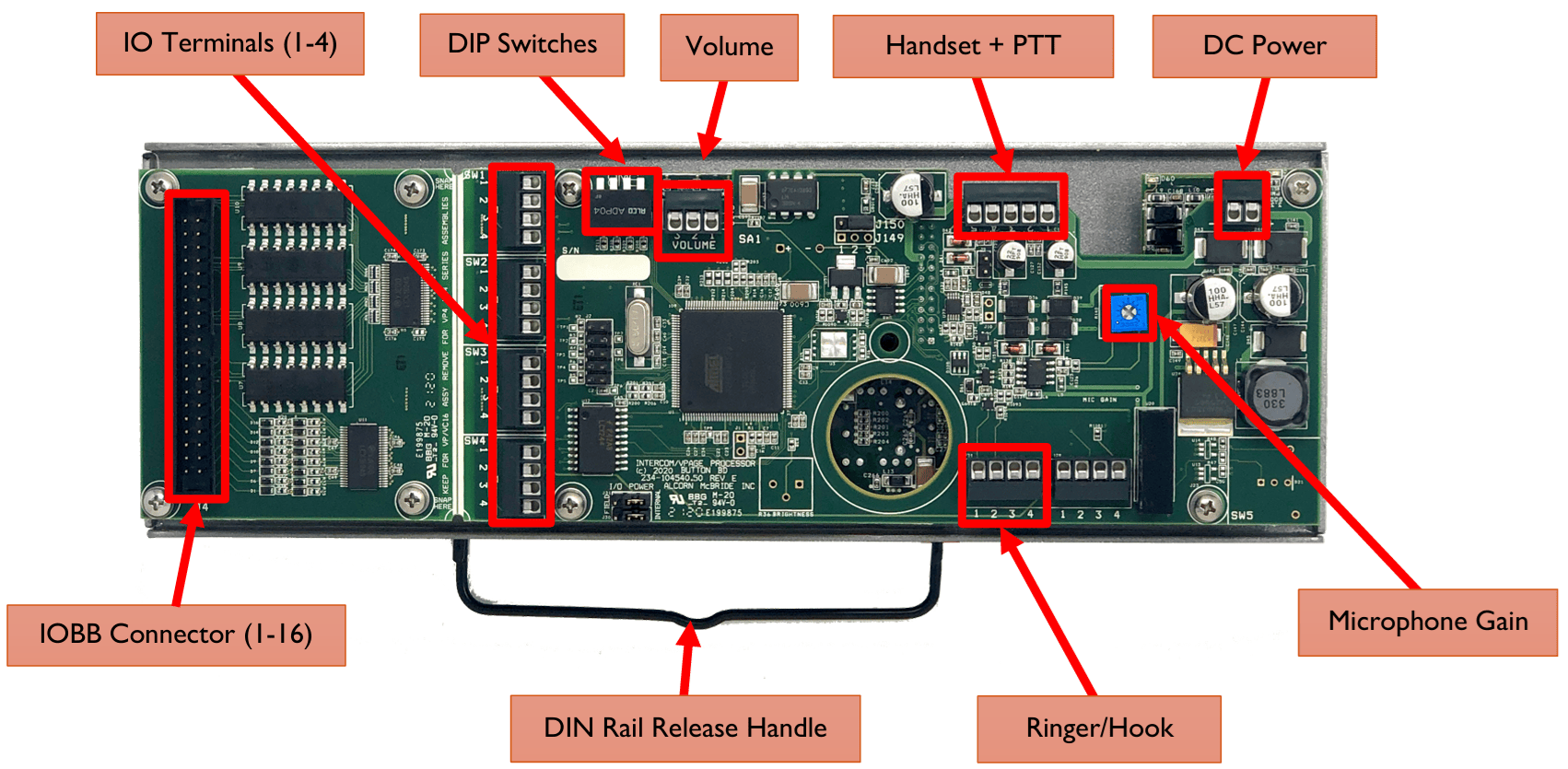
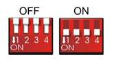
DIP Switches
The configuration DIP switches are located on the side of the V-Com. Changing the states of these switches, either during power-up or normal operation, can alter the behavior of the V-Com. The default position for all the switches for normal operation is OFF (UP).
The V-Com can power up in one of the following modes (based on switches configuration):
- Normal Mode
- Factory Test Mode
- Firmware Update Mode
During power up, the state of some switches (ON or OFF) may result in action. During runtime, toggling the DIP switch (OFF => ON => OFF) may perform a specified action. See the descriptions below.
DIP Switch 1: Link Mode
Runtime
OFF => ON => OFF: Activate/deactivate Link Mode. Toggle once to activate toggle again to deactivate. Link Mode will also exit on successful completion or will auto-exit after 60 seconds (default).
Link Mode can be used in conjunction with Q-SYS to assign station ID, static IP/Port and Q-SYS feedback information to the V-Com. In a sense, this pairs the V-Com with a specific Q-SYS Core.
While Link Mode is active, the green LEDs will illuminate one at a time in a sequential chasing pattern.
DIP Switch 2: Firmware Update Mode / Reset Factory Defaults
Power Up
ON: Enter Firmware Update Mode. In this mode, the V-Com disregards all other settings and all other DIP switches and uses a default IP of 192.168.0.254. The V-Com serves the Firmware Update page at this IP address. For a detailed explanation on updating V-Com firmware, see the Firmware Update section.
To exit Firmware Update Mode, return the switch to OFF position and perform a power cycle.
OFF: Default state of the switch for normal operation.
Note
It’s advised to use AMI Terminal to invoke the firmware update. The V-Page will enter the firmware update mode on the last known IP instead of fixed 192.168.0.254.
Runtime
OFF => ON => OFF: Perform a Factory Reset. All LEDs will light up solid
Warning
Performing a Factory Reset will erase all V-Page settings, including Dante settings!
DIP Switch 3: Factory Test Mode
Power Up
ON: Puts the V-Com into Factory Test Mode for testing purposes only. Factory Test Mode is mainly used for troubleshooting. It is NOT a requirement to program the V-Page as all the parameters can be programmed while operating in the normal mode. While in Factory Test Mode, the V-Com will not fully operate as a paging station.
Note
The V-Com must not be in Firmware Update Mode (DIP Switch 2).
OFF: Default state of the switch for normal operation.
DIP Switch 4: Spare
Power Up/Runtime
ON: Not in use.
OFF: Default state of the switch for normal operation.
Connectors
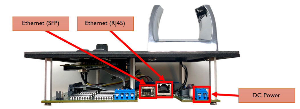
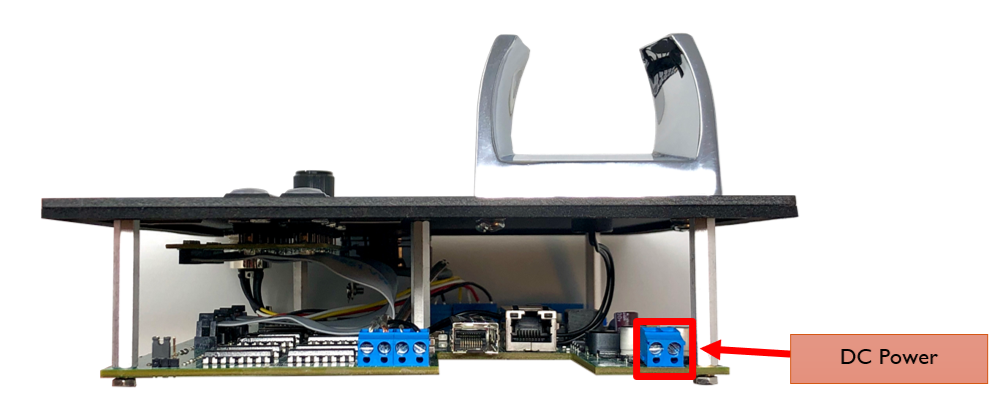
Power
An external power input is provided if you do not use Power-Over-Ethernet (PoE) (circled in red below).
The power input accepts 5 VDC to 37 VDC at 1 A max.
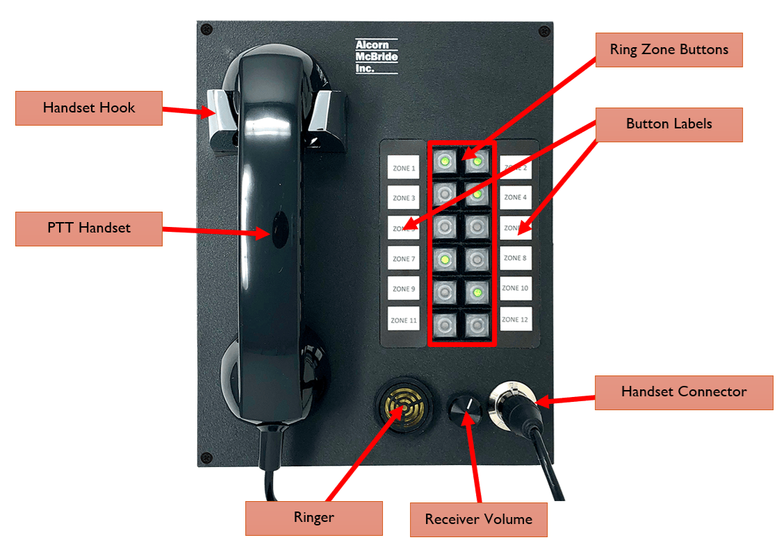
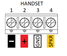
Handset
The handset connector pinouts are shown below. Pin numbers are also printed on the Printed Circuit Board (PCB).
This connector is designed specifically to terminate a panel-mount male 4-pin XLR connector that connects to our V-Com Handset (HANDSET-VC).
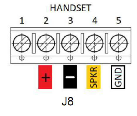
The following 4-pin XLR harness comes with the V-Com VC16K and is wired as follows:
| Phoenix Connector Pin | Signal | 4-Pin Female XLR |
|---|---|---|
| 2 | Microphone (+) | 1 |
| 3 | Microphone (-) | 2 |
| 4 | Speaker (+) | 3 |
| 5 | Speaker (-) | 4 |
Volume
The Volume connector pinout is shown below. Pin numbers are also printed on the bottom of the PCB. The volume control is not used for intercom applications.
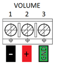
The included volume knob harness should be wired to the phoenix connector as follows:
| Phoenix Connector Pin | Wire Color Code |
|---|---|
| 1 | Black |
| 2 | White |
| 3 | Grey |
Sonalert Ringer & Handset Hook
The Sonalert Ringer and Handset Hook connector pinout is shown below. The input labeled SWHook is where the Hang-up Sensor is connected. Pin numbers are also printed on the PCB.
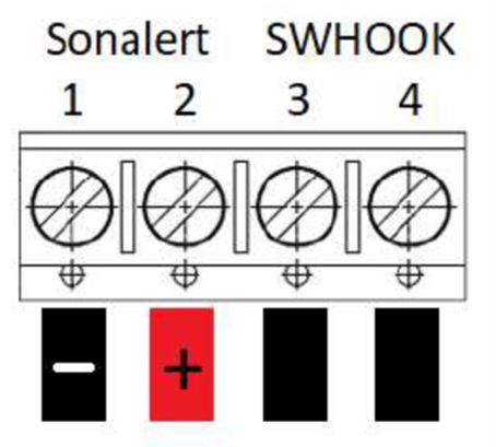
Note
The Handset Hook sensor is a contact closure so wiring polarity is irrelevant. Be sure to observe the + and – labels on the Sonalert when wiring to this connector.
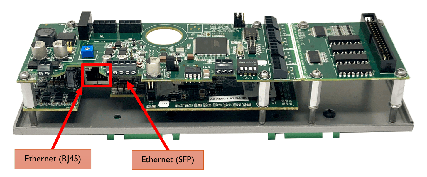
Ethernet (RJ45)
A standard RJ-45 ethernet connector is used for the network connection and PoE.
Ethernet (SFP)
A Small Form-factor Pluggable (SFP) transceiver connector is available to provide support for a fiber-optic alternative to the RJ45 port. Both Single-Mode and Multi-Mode modules are compatible. Make sure that the same SFP module model is used on both ends of the fiber optic connection to ensure compatibility.
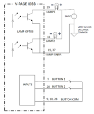
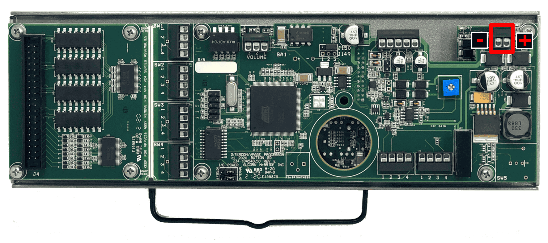
IO Terminals (VC16K Only)
If your custom paging station requires 4 buttons/indicators or less, it’s very simple to interface directly to the IO terminals located on the VP16K main board. The Button inputs require a simple contact closure between pins 1-2 to activate. The lamp outputs apply +12 VDC across the terminals LAMP (-) and LAMP (+) to power your LED indicators.
These terminals are shown below:
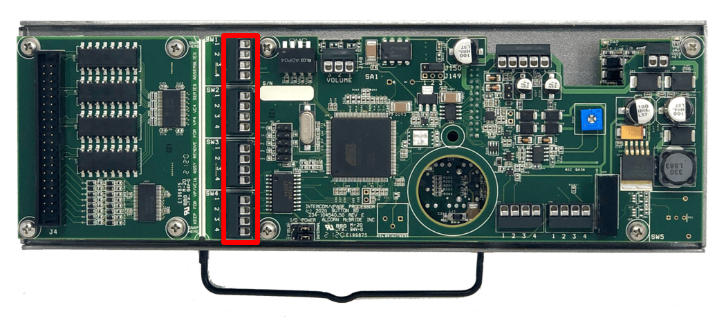
The pinouts of these terminals is as follows:
| Input | SW1 | SW2 | SW3 | SW4 |
|---|---|---|---|---|
| 1 | Button 1 (-) | Button 2 (-) | Button 3 (-) | Button 4 (-) |
| 2 | Button 1 (+) | Button 2 (+) | Button 3 (+) | Button 4 (+) |
| 3 | LAMP 1 (-) | LAMP 2 (-) | LAMP 3 (-) | LAMP 4 (-) |
| 4 | LAMP 1 (+12 V) | LAMP 2 (+12 V) | LAMP 3 (+12 V) | LAMP 4 (+12 V) |
IOBB Interface (VC16K Only)
If your custom intercom station requires more than 4 buttons/indicators, you must use the included IOBB expansion interface that comes included with your VC16K intercom station kit. The Phoenix terminals of the IOBB make it easy to terminate your externally mounted pushbuttons and indicator lamps.
The pinout of the IOBB interface is as follows:
| Pin | Function | Pin | Function |
|---|---|---|---|
| 1 | BUTTON 1 | 20 | BUTTON 9 |
| 2 | BUTTON 2 | 21 | BUTTON 10 |
| 3 | BUTTON 3 | 22 | BUTTON 11 |
| 4 | BUTTON 4 | 23 | BUTTON 12 |
| 5 | BUTTON 5 | 24 | BUTTON 13 |
| 6 | BUTTON 6 | 25 | BUTTON 14 |
| 7 | BUTTON 7 | 26 | BUTTON 15 |
| 8 | BUTTON 8 | 27 | BUTTON 16 |
| 9 | BUTTON COM | 28 | BUTTON COM |
| 10 | BUTTON COM | 29 | LAMP 9 (-) |
| 11 | LAMP 1 (-) | 30 | LAMP 10 (-) |
| 12 | LAMP 2 (-) | 31 | LAMP 11 (-) |
| 13 | LAMP 3 (-) | 32 | LAMP 12 (-) |
| 14 | LAMP 4 (-) | 33 | LAMP 13 (-) |
| 15 | LAMP 5 (-) | 34 | LAMP 14 (-) |
| 16 | LAMP 6 (-) | 35 | LAMP 15 (-) |
| 17 | LAMP 7 (-) | 36 | LAMP 16 (-) |
| 18 | LAMP 8 (-) | 37 | LAMP GND (-) |
| 19 | LAMP GND (-) | 38 | N/A |
Note
The lamp outputs are optically isolated, capable of sinking up to 50mA at 30 VDC max each.