Getting Started
Alright, time to roll up your sleeves and get to work! This section will guide you through basic concepts that will help you get on your way with BinloopX.
A/V Module Installation
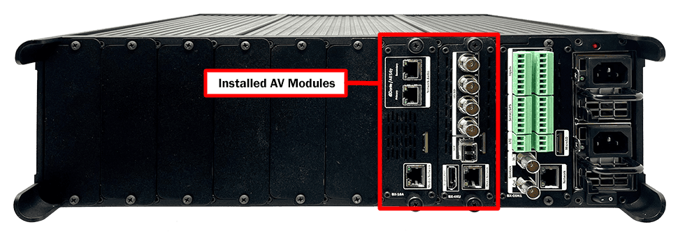
The BinloopX is a modular platform with 8 A/V module slots. If you order your BinloopX pre-configured, we install these modules for you at the factory. However, if you order these components separately (perhaps at a later time to expand the capabilities of a BinloopX), you will need to install these modules yourself.
Thankfully, this process is extremely easy. First, you need to remove two screws from the cover plate of an empty slot. This will expose the slot so that a new A/V module can be inserted.
![]()
Next, insert the new A/V module into the empty slot and then tighten the thumb screws to secure the module.
Once you have installed the A/V modules you wish to use, proceed to the next section to properly connect your BinloopX.
Wiring and Connectivity
A few connections are required to experience the core functionality of BinloopX.
Power
Our engineers are working around the clock to eliminate the need for those pesky Electrons. However, until they inevitably succeed, BinloopX needs power to work properly.
You'll want to start by connecting the BinloopX power supply to a 110-240VAC power source. This product has a redundant power supply so, while it will work just fine with only one power connection, it is recommended that you connect both power supply inputs. Otherwise, the power supply will emit an intentionally obnoxious BEEEEEEP and quickly drive you mad.
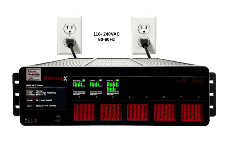
Once you have connected the power source, BinloopX can be powered up by simply flipping the power switch to the ON position.
HEY!!! What are you doing?!? We didn't actually say to power it up yet, but you went ahead and did it anyway didn't you?!?! [Head Slap] Alright... clearly you're excited so I guess we'll cut you some slack, but could you at least TRY to follow instructions next time?
Network
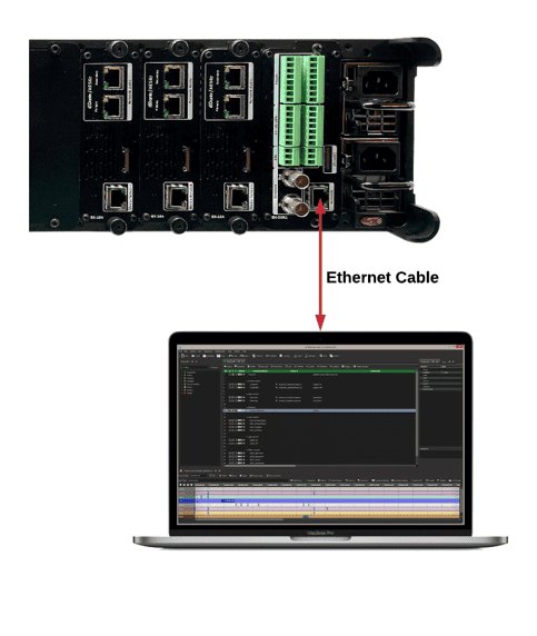
While BinloopX sure looks pretty when you power it up, network connectivity is required to actually make it do magical things. The goal here is to interface BinloopX to your Windows or macOS computer running our WinScript Live software. This application empowers you to configure, program, and load media content to the unit over the network connection.
To make this connection, you'll use need a standard RJ45 Ethernet patch cable. You'll want to connect the main Network port of BinloopX to your network switch or computer. To be clear, this network port is located on the BX-CON1 controller module located directly next to the power supply. When the unit is powered on, you will see a link indicator illuminate on the ethernet port to indicate a good network connection.
Network Configuration
Now that we're good to go with connections, we just need to do a little bit of configuration before we can connect your computer to BinloopX. Before we get started, it's helpful to know that BinloopX ships with the following default IP address configuration:
| BinloopX Network Port | |
|---|---|
| IP Address | 192.168.0.254 |
| Subnet Mask | 255.255.255.0 |
If you're at ease in the world of networking, you can easily adjust these settings for BinloopX to operate on an existing network. For more information on how to access the network configuration menu, see the Display and Navigation section of this User's Guide.
For those that just wish to connect a computer directly to BinloopX, the easiest way is to set your computer to a static IP address that is compatible with BinloopX's default network settings. For example, this configuration would work nicely for your computer:
| Computer Network Port | |
|---|---|
| IP Address | 192.168.0.100 |
| Subnet Mask | 255.255.255.0 |
Configuring Static IP - Windows 10
-
Right-click on the Windows icon in the bottom-left and select Network Connections
-
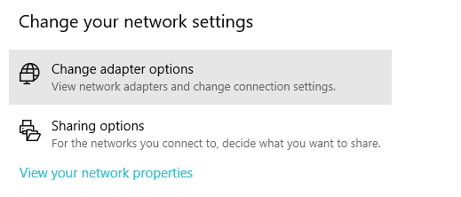
Select Change adapter options
-
Right-click on the network interface that is connected to the BinloopX and select Properties
-
Select Internet Protocol Version 4 (TCP/IPv4) from the list of items and click the Properties button below.
-
Select Use the following IP address, enter the IP address as 192.168.0.100, and enter the Subnet Mask as 255.255.255.0 as indicated in the screenshot below:

- Click the Ok button to apply the static IP address.
Configuring Static IP -- OS X
- Click on the network icon in the OS X menu bar and select Open Network Preferences.

-
Select the network interface that is connected to the BinloopX from the available interfaces on the left.
-
Configure the network interface Manually, specify an IP address of 192.168.0.100, and a Subnet Mask of 255.255.255.0 as indicated in the screenshot below.
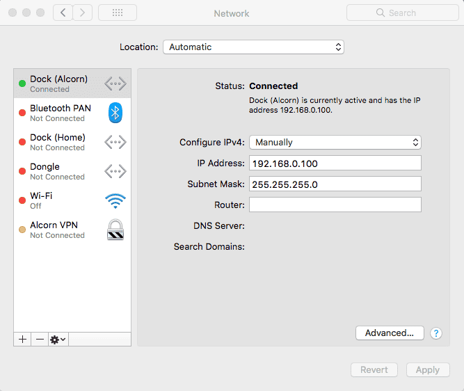
- Click Apply to enable the new static IP configuration
Creating a BinloopX Project
At this point, everything should be wired up, configured, and ready to go. The next step is to create a new script and then connect to the BinloopX using our WinScript Live software. Once connected, you will have access to transfer media content, configure, and control the BinloopX unit.
Before we can get started, you'll want to make sure to install the latest version of WinScript Live on your Windows or macOS computer. This software can be downloaded for free from our website at www.alcorn.com.
Once WinScript Live is installed, follow these instructions to create a project for your BinloopX:
-
Go ahead and power on the BinloopX using the power switch. No really... it's cool. I'm sorry I yelled at you earlier, even though you kind of had it coming.
-
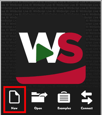
Launch WinScript Live and click the New button on the splash screen
-
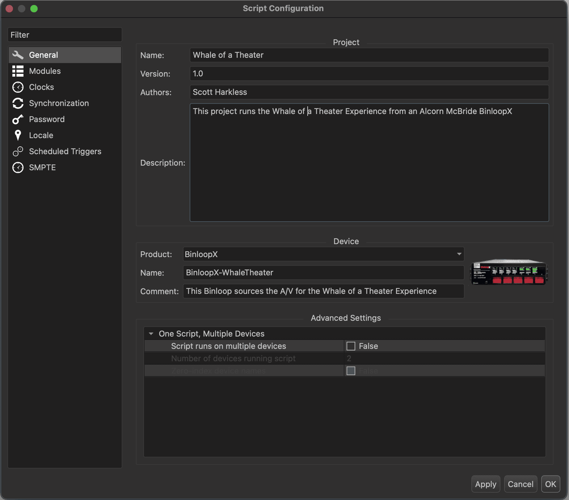
Select BinloopX as the Product and then enter a device Name in the properties below (i.e. BinloopX-WhaleTheater). Although it's not required, this is also a good opportunity to name your WinScript project file and add any comments that describe the purpose of this project and hardware. If you don't know the purpose, you should probably figure it out before the client realizes this and starts to wonder why they hired you.
-
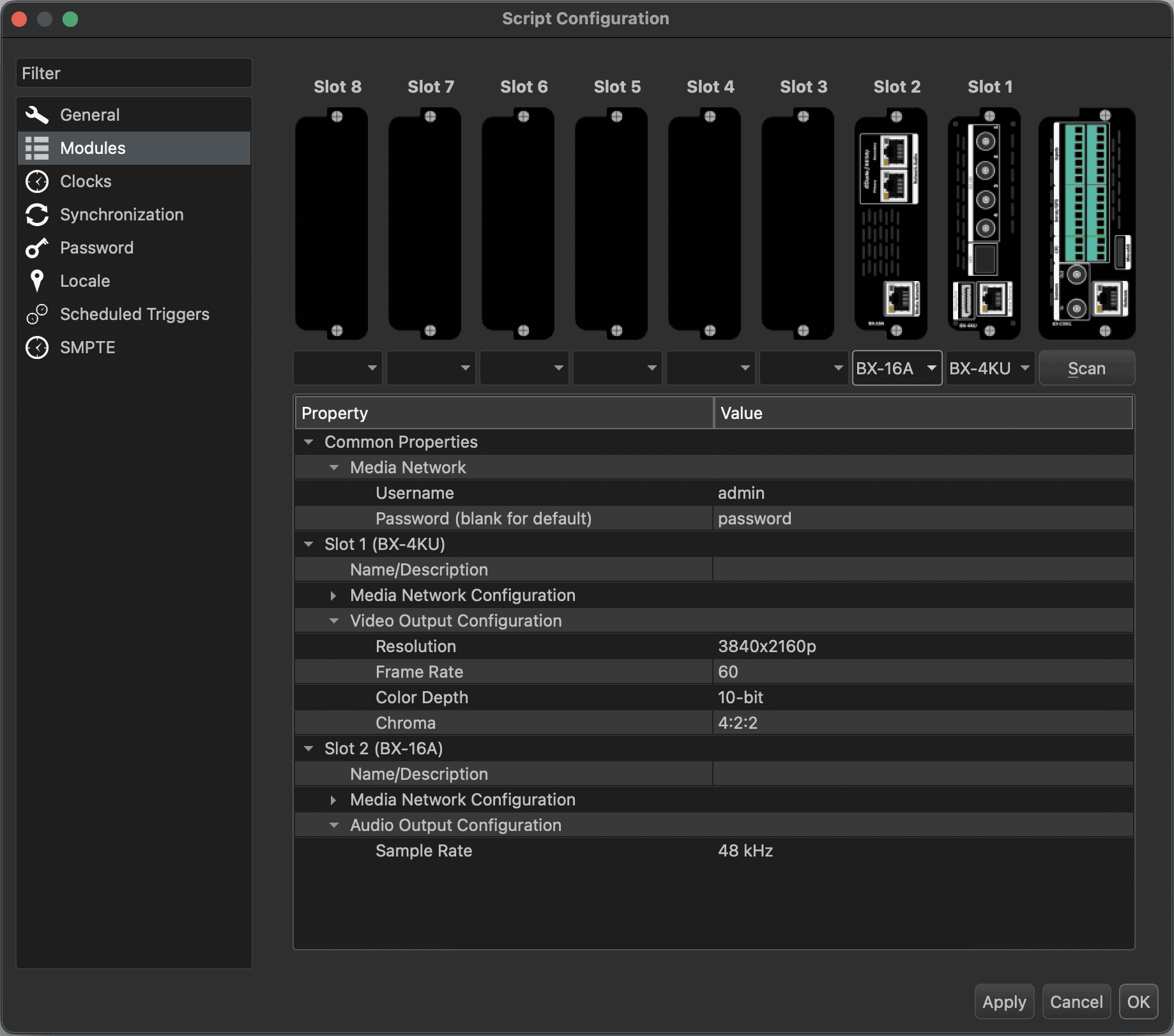
Next, select the Modules section on the left to bring up the BinloopX Module Configuration.
-
Now, we need to specify which modules are installed within your BinloopX. Use the dropdown below each A/V Module Slot to select the modules you have installed. Click Next to proceed to the Module Properties screen.
Alternatively, you can automatically detect the modules within your BinloopX using the Scan button. This method will scan your network interface for the BinloopX, request its current module configuration, and automatically select the correct modules for each slot.
-
Specific settings for each module can be configured in the Property list below. This allows you to do things like assign a name to each module, configure the Media Network port, specify video output settings, or audio sample rate. If you choose to assign a name to a module, it will appear at the top of the module's status display like so:

-
While we're at it, go ahead and select the Clocks section on the left of the Script Configuration screen.

-
These settings allow you to configure the master clock of the BinloopX, which is used as a timing reference by the show control engine. For example, the Frame Rate you select here will determine the timing reference used by timed sequences. You can also select an external Source as a synchronization reference for this clock. It is extremely common to lock a BinloopX to a PTP clock being generated by a V16X, PLC, or a stand-alone Master Clock source. This is incredibly useful if you need precisely timed control of your BinloopX, or if you are synchronizing your BinloopX with other devices such as RidePlayers or BinloopX units. If this circumstance doesn't apply to your project, you can just leave this setting on None and the BinloopX will live in blissful ignorance of the world around it and just generate its own internal clocks.
-
Click OK to finish creating the project.
-
Now would be a great time to Save the project before a squirrel stuffs an acorn between the high-voltage terminals of your building's transformer and learns the true meaning of Ohm's Law.
Connecting to the BinloopX
We still have more work to do before we do anything really interesting, but now is a good time to get WinScript Live and the BinloopX connected to each other.
The way this works is pretty simple. In the previous section when you created this project, you gave the BinloopX a unique name like BinloopX-WhaleTheater. The first time we connect to an actual BinloopX with this project, we will name it to match the project; pairing them for life... or at least until you decide to use it for something else.
- Let's start by clicking the Connect button located in the Menu bar at the top of WinScript.
-

-
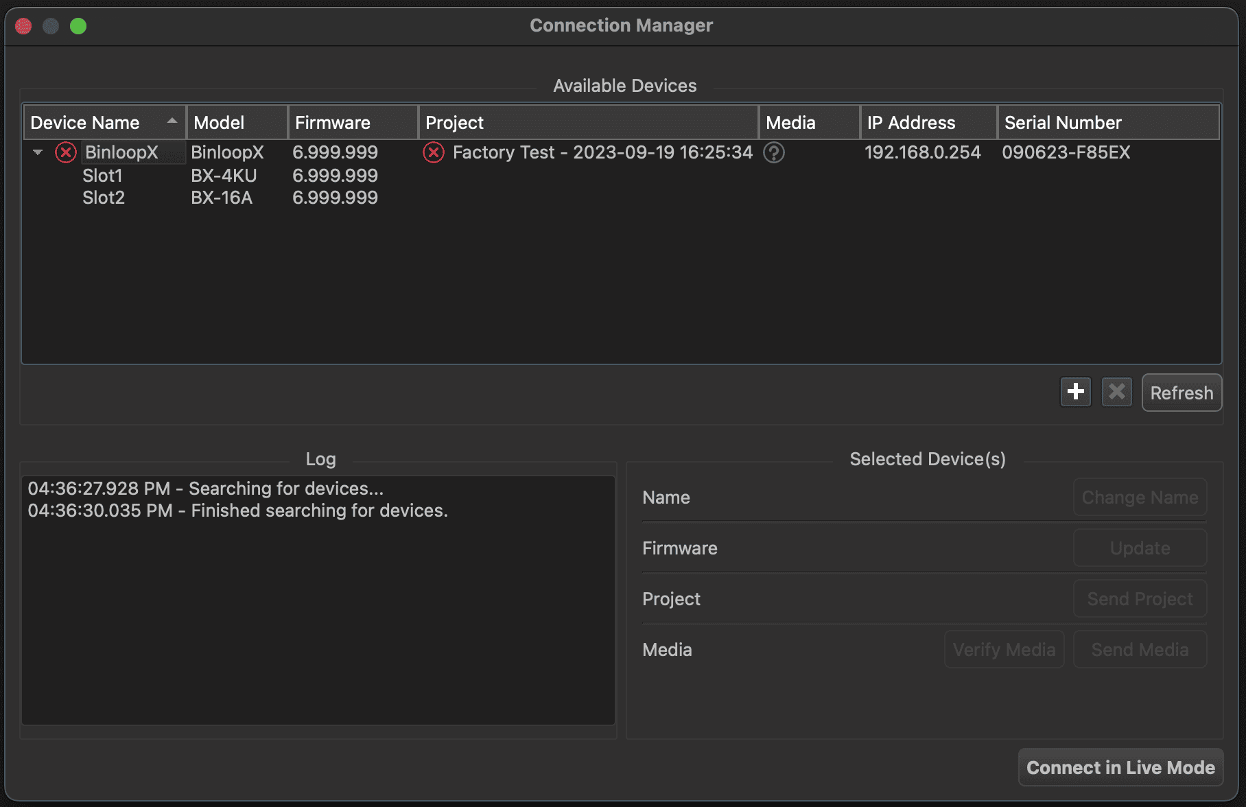
The Connection Manager screen will appear and scan any networks that your computer is connected to. If you actually bothered to read the Network Configuration section, your BinloopX should show up like this:
-
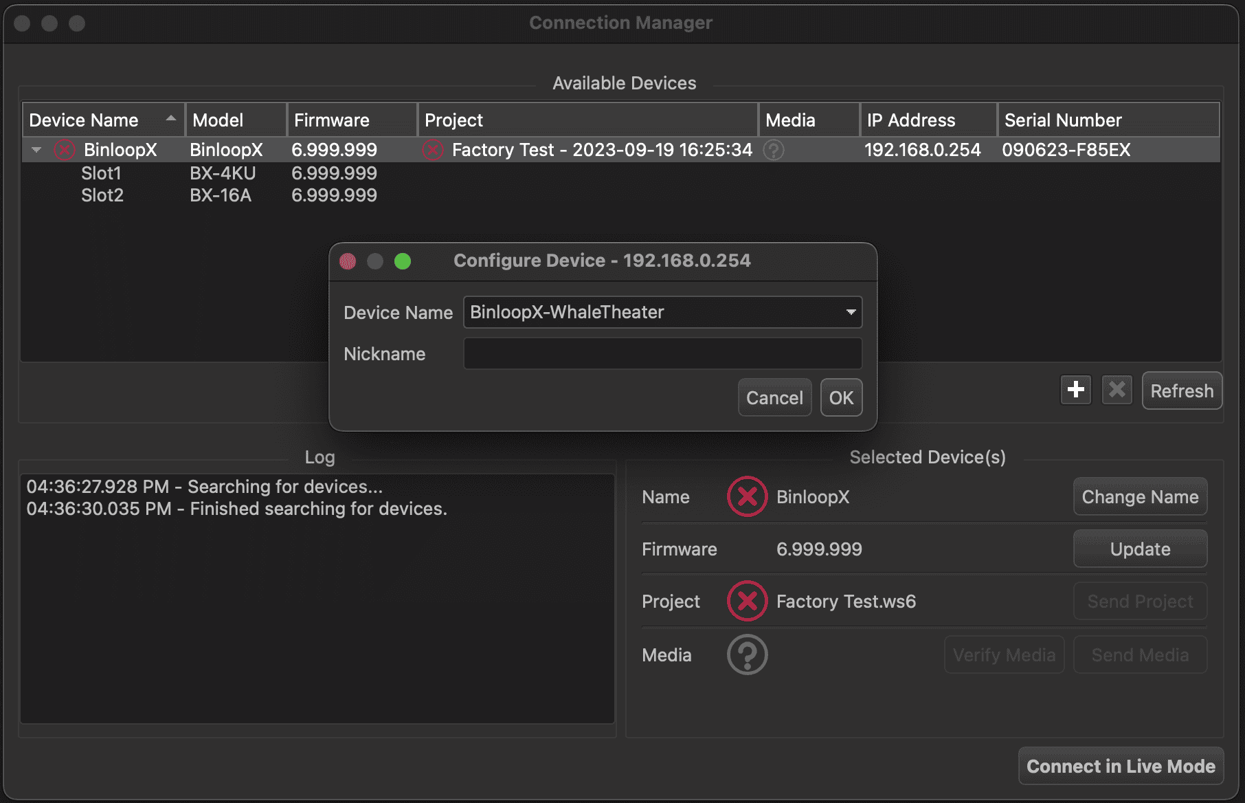
Click on the BinloopX entry to select it, and then click the Change Name button.
-
-
The name assigned to your project (i.e. BinloopX-WhaleTheater) will automatically appear in the Device Name section. Click OK to assign this name to the BinloopX hardware.
NOTE: Changing the name of the BinloopX basically reassigns it to your project. It's previous life will become but a distant memory, and it will find new purpose through you...assuming you've figured out what that purpose is yet. But seriously... don't do this with a BinloopX that someone else is actually using or it will probably make them angry.
-
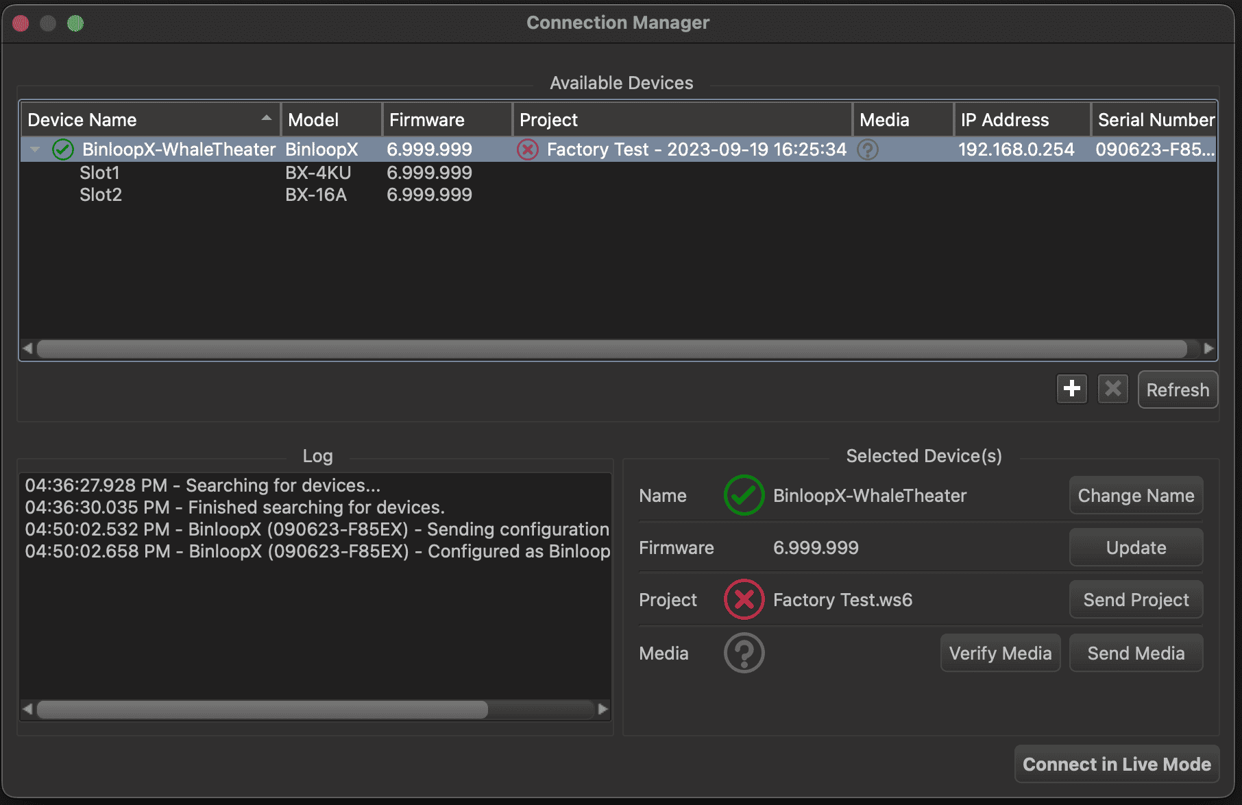
Once the BinloopX is configured with the new name, you get a nice "green check of confidence" to show that this BinloopX is now paired with your project. Click on the Send Project button to transfer your project to the unit. The BinloopX will reboot once the transfer is complete.
-
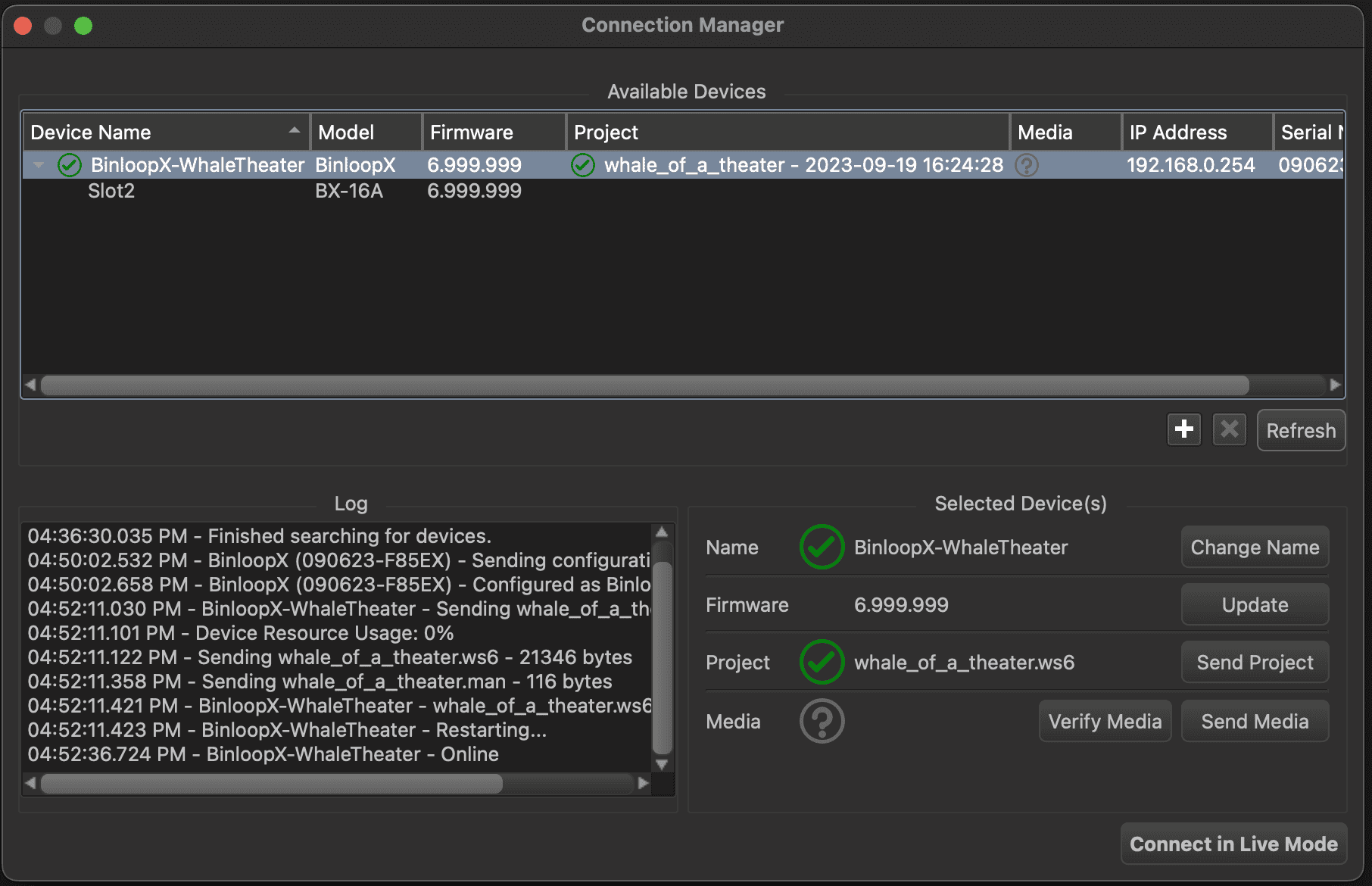
Once the BinloopX unit reboots, it will load your project file and you'll see another "green check of confidence" indicating that the project file loaded to the hardware matches the project file you have open in WinScript Live.
NOTE: The green check icons are a powerful tool when it comes to sending and retrieving projects from the BinloopX. If the BinloopX is paired with another project, the Name icon will indicate this to you. If it is running a newer/older project file, the project status icon will indicate this with a red X. If the firmware does not match your version of WinScript, this will be indicated as well. Bottom line...green good...red bad... you know the drill.
-
Click Connect in Live Mode to establish a live mode connection with the BinloopX. This will allow you to monitor and edit the BinloopX project in real time for the remainder of this Getting Started guide.
Playing Media
All of our BinloopX A/V playback modules come preloaded with audio or video test clips. This section will show you how to play them while covering the basics of playback control in WinScript Live.
Playing Video
Follow these instructions if you have one or more BX-4KU video modules installed within your BinloopX. If you do not, feel free to skip ahead to the Playing Audio section.
-
First, we need to add the video test clip to our WinScript project. In the Resources pane on the left, expand the Modules resource and then expand the resource tree for the BX-4KU module that you want to play.
-
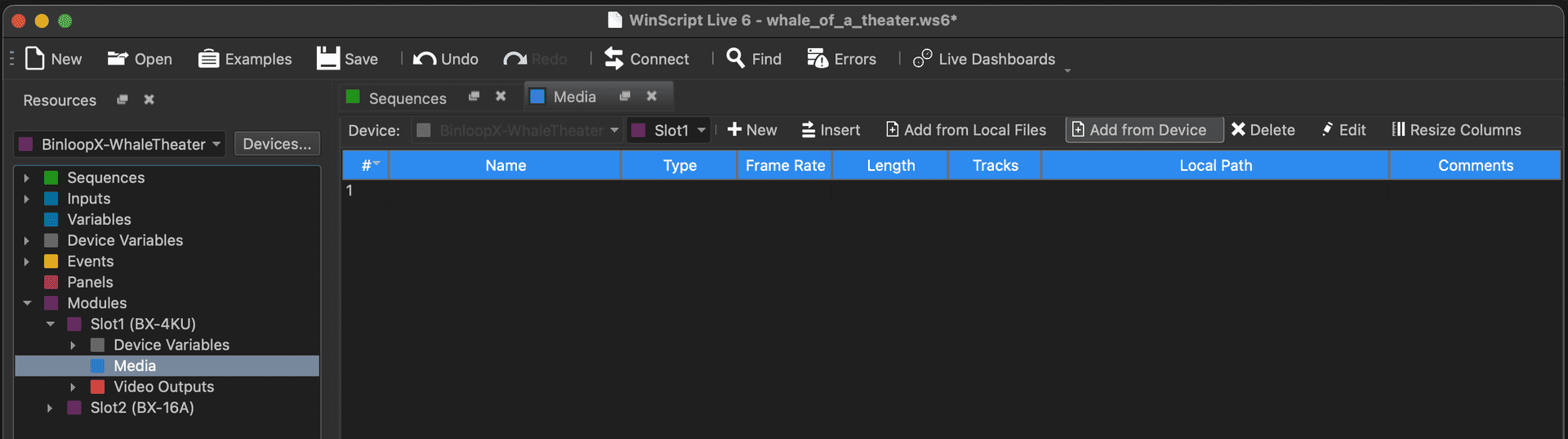
Double-click on the Media resource for this module to view the Media list.
-
Click the menu option labeled Add from Device.
-
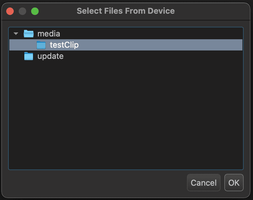
Select the video clip named testClip and click OK.
-
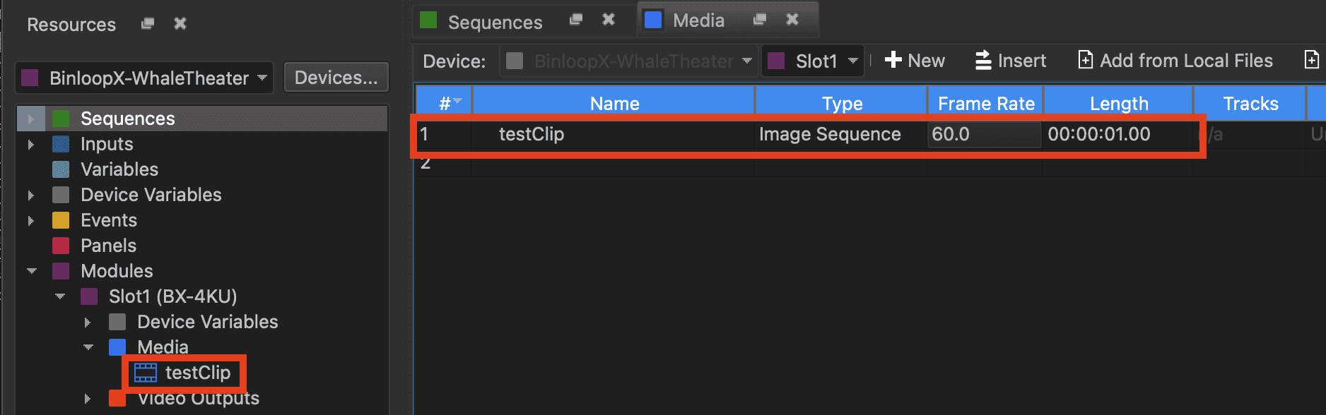
This video should now appear in the Media list and resource tree:
-
Next, select the Sequences tab to view the sequence list and create a new sequence by clicking the New button in the menu at the top of the list. Enter Timeline_TestVideo as the sequence name and select Timed as the sequence type.

-
Click OK to create the sequence.
-
Using the Resources section on the left of WinScript Live, expand the Media resources of the BX-4KU video module you wish to play. You should see the testClip resource that you added in step #4.
-
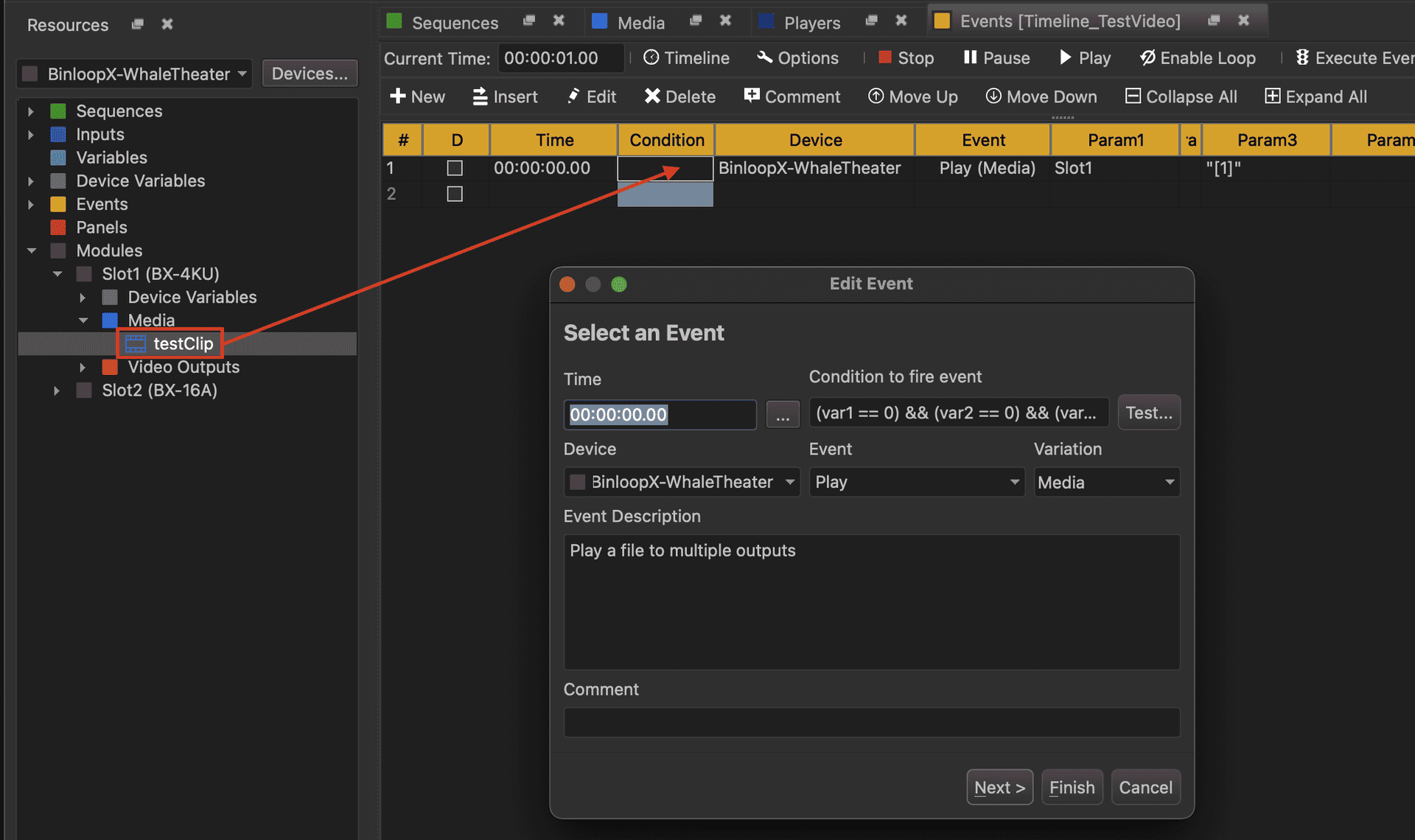
Click-and-hold a test clip and drag it onto the Sequence that you just created. Once you release the media clip into the sequence, the event editor will appear prompting you for more details.
-
You can see the the BinloopX device and the Play event have been automatically entered as a result of dragging over the media resource. Click the Next button to proceed to the next step in the Edit Event screen.
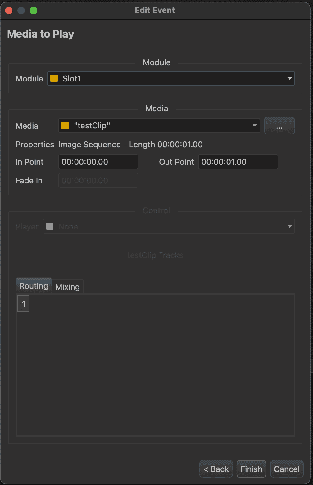
-
Here, you can see that the BX-4KU slot and media clip name have also been pre-filled. Click Finish to complete the event.
-
The event will now appear within the sequence like so:
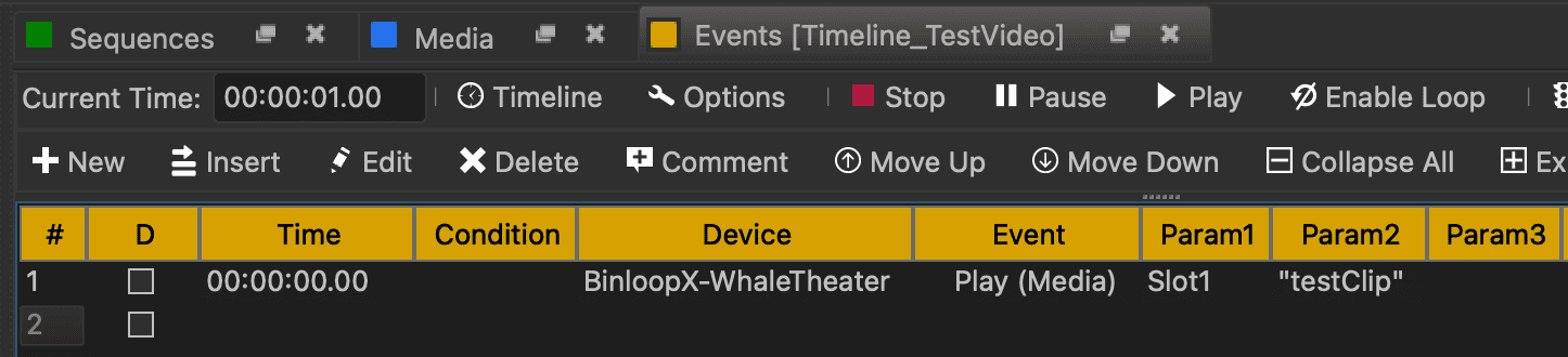
-
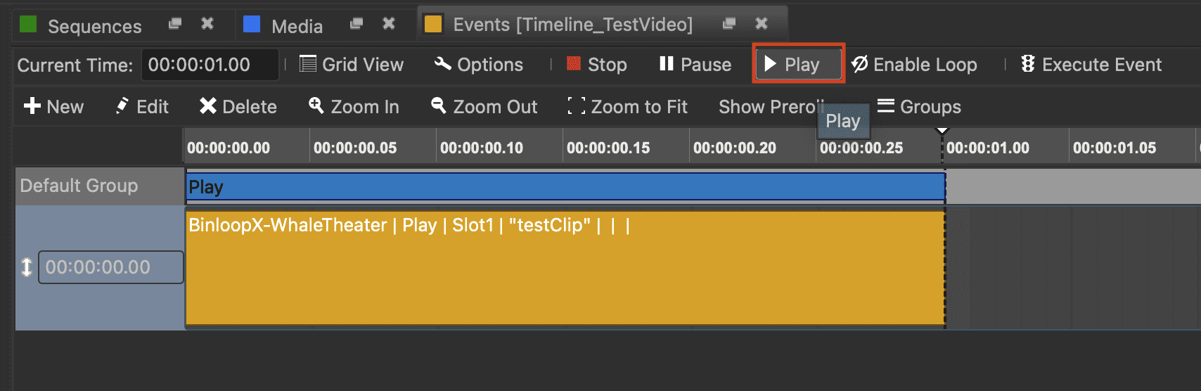
If you wish, this sequence can be viewed as a timeline by clicking the Timeline icon in the menu bar at the top of the sequence view. If you also click Zoom to Fit button, it will expand the timeline view horizontally allowing you to see the duration of the Play event that you just created.

-
Since you are connected with the BinloopX, you can click the Play button at the top of the sequence view to play the sequence.
-
If you look at the front-panel of the BinloopX, the display of module you are controlling will show that the test clip is playing.
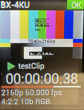
-
Let's learn another common way to control this sequence. Click on the Sequences tab to view the sequence list. Click on the Loop icon to the left of the sequence named Timeline_TestVideo to enable looping and then click on the Play icon. If you monitor the front-panel of the BinloopX, you'll see that the test video is now looping.
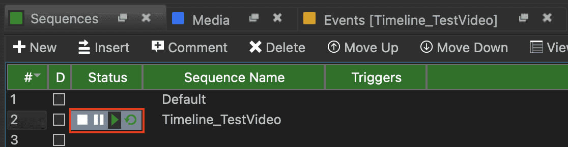
-
Click on the Stop icon to the left of the sequence named *Timeline_TestVideo to stop playback.
Now, whenever you play the sequence Timeline_TestVideo there will be video available on the SDI and DisplayPort outputs of the BX-4KU video module. All you need to do is connect a compatible display, projector, or LED wall processor to view the content.
To keep this introduction simple, this Getting Started guide relied upon test content that was pre-loaded to the BX-4KU video module at the factory. For information on how to create and load your own video media, refer to the Media section of the BX-4KU module documentation.
Congratulations! You have now learned the fundamentals of playing video content within the BinloopX. If you have a BX-16A audio module installed within your BinloopX, the next section will demonstrate how to play audio content.
Playing Audio
Follow these instructions if you have one or more BX-16A audio modules installed within your BinloopX.
-
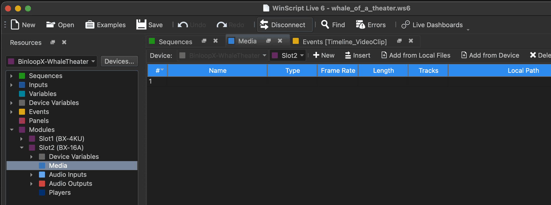
First, we need to add the audio test clip to our WinScript project. In the Resources pane on the left, expand the Modules resource and then expand the resource tree for the BX-16A module that you want to play.
-
Double-click on the Media resource for this module to open the Media list.
-
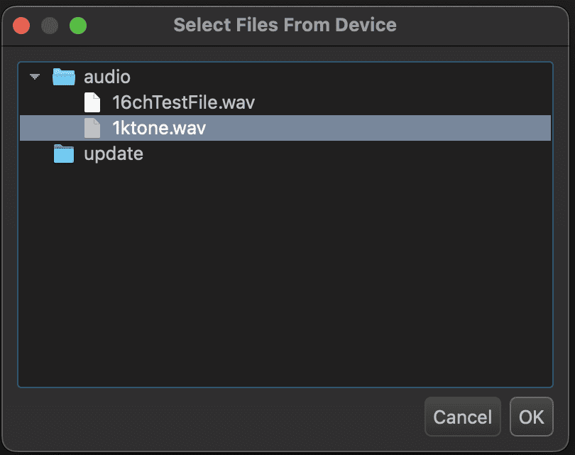
Click the menu option labeled Add from Device.
-
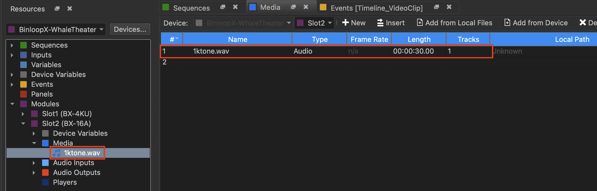
Select the audio clip named 1ktone.wav and click OK.
-
This audio clip should now appear in the Media list and resource tree:
-
Next, we're going to create a special type of resource called a Player. Players make it really easy to configure how audio files are mapped to audio outputs as well as control a specific instance of audio media playback. This is incredibly useful, especially in common situations where multiple instances of audio playback are being mixed/layered on the same audio outputs. In the Resources list on the left, browse to the Players resource for the BX-16A module you wish to control and double-click to view the Players list.

-
Click on the New button at the top of the players list to create a new player.
-
Enter Player_Test as the player's name. The matrix below represents how the tracks of any WAV file that the player plays are routed to the physical audio outputs of the BX-16A module. For example, a mono WAV file only contains 1 track so it's routing would be determined only by the 1 column, a stereo WAV file would be routed by the 1 and 2 column, and multi-track WAVs would use anywhere between 3 to 64 tracks. The test clip that will be played from this player resource is a mono track, so let's configure this player to route Track 1 to audio outputs 1-3 like this:

-
Click OK to finish creating the player.

-
Next, select the Sequences tab to view the sequence list and create a new sequence by clicking the New button in the menu at the top of the list. Enter Timeline_TestAudio as the sequence name and select Timed as the sequence type.
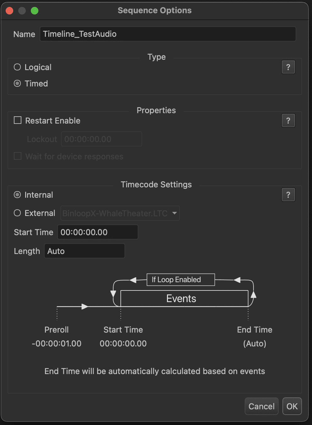
-
Click OK to create the sequence.
-
Using the Resources section on the left of WinScript Live, expand the Media resources of the BX-16A that you wish to play audio. You should see the 1ktone.wav resource that you added in step #4.
-
Click-and-hold the 1ktone.wav media clip and drag it onto the Sequence that you just created. Once you release the media clip into the sequence, the event editor will appear prompting you for more details.

-
You can see the the BinloopX device and the Play event have been automatically entered as a result of dragging over the media resource. Click the Next button to proceed to the next step in the Edit Event screen.
-
Here, you can see that the BX-16A slot and media clip name have also been pre-filled. Select Player_Test as the player you wish to use. Using this player will automatically route the audio of the test clip to the outputs you configured when you created the player. If you ever want to change the gain levels of a player, it will retain those levels. Also, if you ever want to stop playback, all you have to do is tell this player to Stop. Click Finish to complete the event.
NOTE: You are not required to use a Player to playback an audio clip, however there are some drawbacks to consider. First, you will have to manually route the file tracks to the audio outputs within the event. Second, you will have to manually specify the gain levels of each track within the event. Last but not least, there is potentially no way to stop playback of the clip without affecting playback of other files. You have the option of stopping playback of any file routed to an audio output, but this could easily affect multiple files and might not be ideal for your situation. Using players is good practice if you want to streamline your show control programming and have maximum flexibility.
-
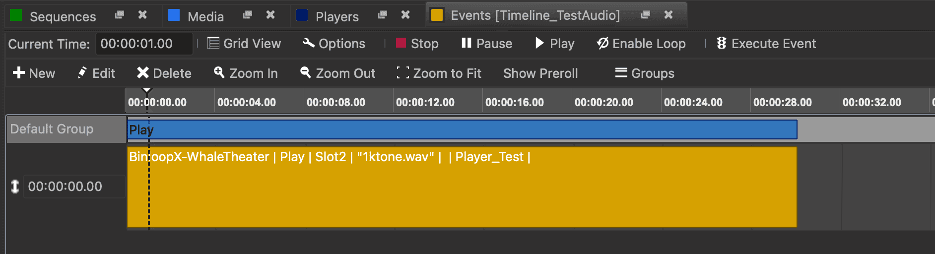
The event will now appear within the sequence like so:

-
If you wish, this sequence can be viewed as a timeline by clicking the Timeline icon in the menu bar at the top of the sequence view. If you also click Zoom to Fit button, it will expand the timeline view horizontally allowing you to see the duration of the Play event that you just created.
-
Since you are connected with the BinloopX, you can click the Play button at the top of the sequence view to play the sequence.
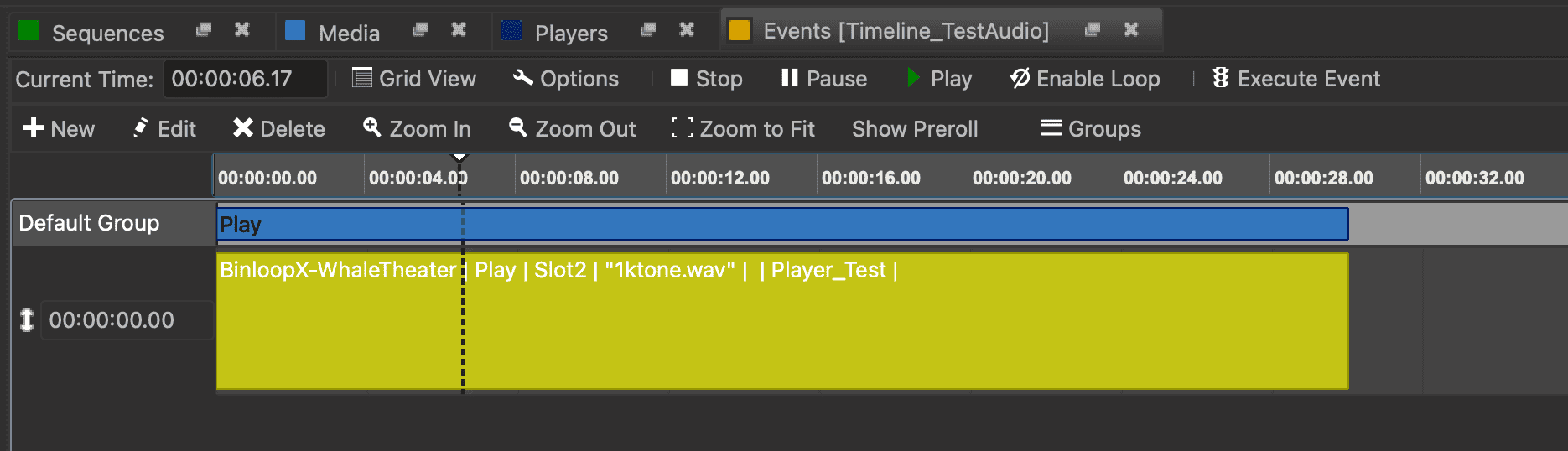
-
If you look at the front-panel of the BinloopX, the display of module you are controlling will show that the test clip is playing.

-
Let's learn another common way to control this sequence. Click on the Sequences tab to view the sequence list. Click on the Loop icon to the left of the sequence named Timeline_TestAudio to enable looping and then click on the Play icon. If you monitor the front-panel of the BinloopX, you'll see that the test video is now looping.

-
Click on the Stop icon to the left of the sequence named *Timeline_TestAudio to stop playback.
At this point, playing the sequence Timeline_TestAudio will result in audio being sourced on the audio outputs you configured in step #8. Listening to this audio will require you to connect the BinloopX to Dante/AES67 network audio device. For more information on this topic, refer to the Network Audio section of this guide.
Also, it's important to point out that this Getting Started guide relied upon the test media that is factory pre-loaded on the BX-16A audio module. For information on how to create and load your own audio media, refer to the Media section of the BX-16A documentation.
Congratulations! You have now learned the fundamentals of playing audio content within the BinloopX.