Wiring Guide
The purpose of this guide is to provide more detail on how to wire peripherals up to the general purpose digital IO that's available on many Alcorn McBride products.
Digital Inputs
Voltage vs. Contact Closure
Every Alcorn McBride device equipped with digital inputs has the ability to operate them in Voltage or Contact Closure mode. The main reason for selecting one mode over the other usually comes down to the distance the IO device (button, relay, etc.) is from the unit, but there may be other factors as well depending on the circumstances of the installation. To help you decide the best approach, we've listed the advantages and disadvantages below.
Voltage Mode
Using Voltage Inputs instead of Contact Closures will add complexity to the wiring but will provide greater reliability over long distance cable runs.
Advantages
- The installer can overcome long distances when connecting contact closures by using higher voltage sources to compensate for resistance in wiring.
- Inputs can be completely isolated from one another.
Disadvantages
- The installer must provide an external power supply for the contact closure(s).
Contact Closure Mode
Using Contact Closures over Voltage Inputs provides a simple installation but limits cabling distance.
Advantages
- Contact closure installations require only wiring and contacts.
- No external power supply is required.
Disadvantages
- To be reliable, the contact closure must be located close (10-20 ft) from the unit.
- The wiring will not be isolated. Errors and problems in any circuit could affect other contact closure inputs.
- A high voltage short to this wiring could damage the product.
Input Configuration
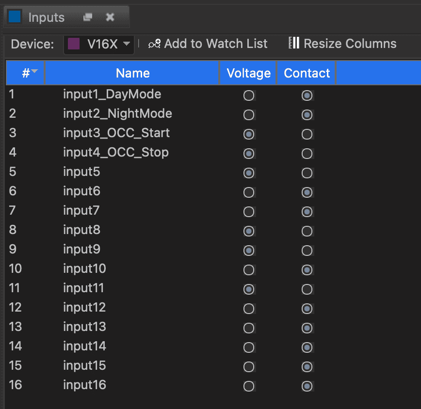
The operating mode of our digital inputs are configured by WinScript Live software. Select Resources from the main menu bar, and then select Inputs. The window shown below lets you select the input type for each input. Notice the input name may be changed, and a comment describing the input’s use may be added. This makes it easier to remember what you were trying to do when you look at the script again later!
Input Wiring
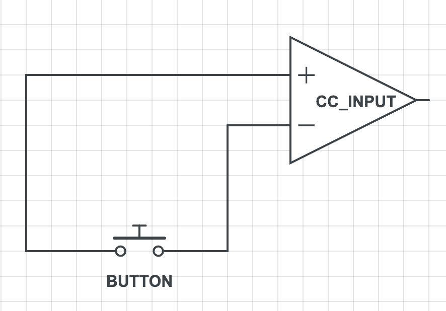
Connecting a Voltage input
-
Attach the appropriate wire from the Input(+) signal pin to the positive terminal of the external power supply.
-
Connect the negative terminal of the external power supply to one of the terminals of the contact closure or push button.
-
Connect the appropriate Input(-) pin to the other terminal of the contact closure.

NOTE: When wiring in this configuration, it is OK to bus multiple Input(+) terminal pins to the external power supply.
Connecting a Contact Closure input
-
Attach the appropriate wire from the Input(+) signal pin to one of the terminals of the external contact.
-
Connect the appropriate Input(-) Return pin to the other terminal of the external contact.
NOTE: DO NOT bus multiple Input(+) or Input(-) terminal pins to each other when operating in Contact Closure mode. Each contact input must have it's own discrete wiring.
Digital Outputs
Output Configuration
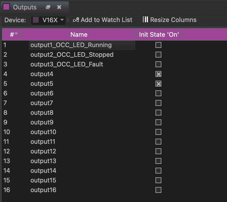
The initial state of each output may be configured by WinScript Live to be open or closed when the script is started. The outputs are configured by WinScript Live software. Select Resources command from the main menu bar then select Outputs. The window shown below opens. You may change the name, define the initial state of the output, and add a comment to describe the output’s use.
Output Wiring
Non-inductive Load
Non-inductive loads are resistive. Incandescent bulbs, LEDs and filament lamps do not require additional hardware. Loads that do not have inductors, coils or transformers are non-inductive loads.
-
Attach the appropriate Output(+) pin on the Digital Outputs connector to the positive terminal of the external power supply.
-
Connect the corresponding Output(-) Return pin to the positive terminal of the device that is receiving the output signal.
-
Connect the negative terminal of the device that is receiving the output signal to the negative terminal of the external power supply.

NOTE: When using LEDs like the illustrated example, be sure that the LED has an inline current-limiting resistor. Sometimes these are integrated into the LED indicator. When this is the case, the indicator will be rated for a specific voltage (i.e. 12VDC, 24VDC, etc.). If this is not indicated, you will need to calculate the resistor value based on the LED specifications, power supply voltage, and desired current.
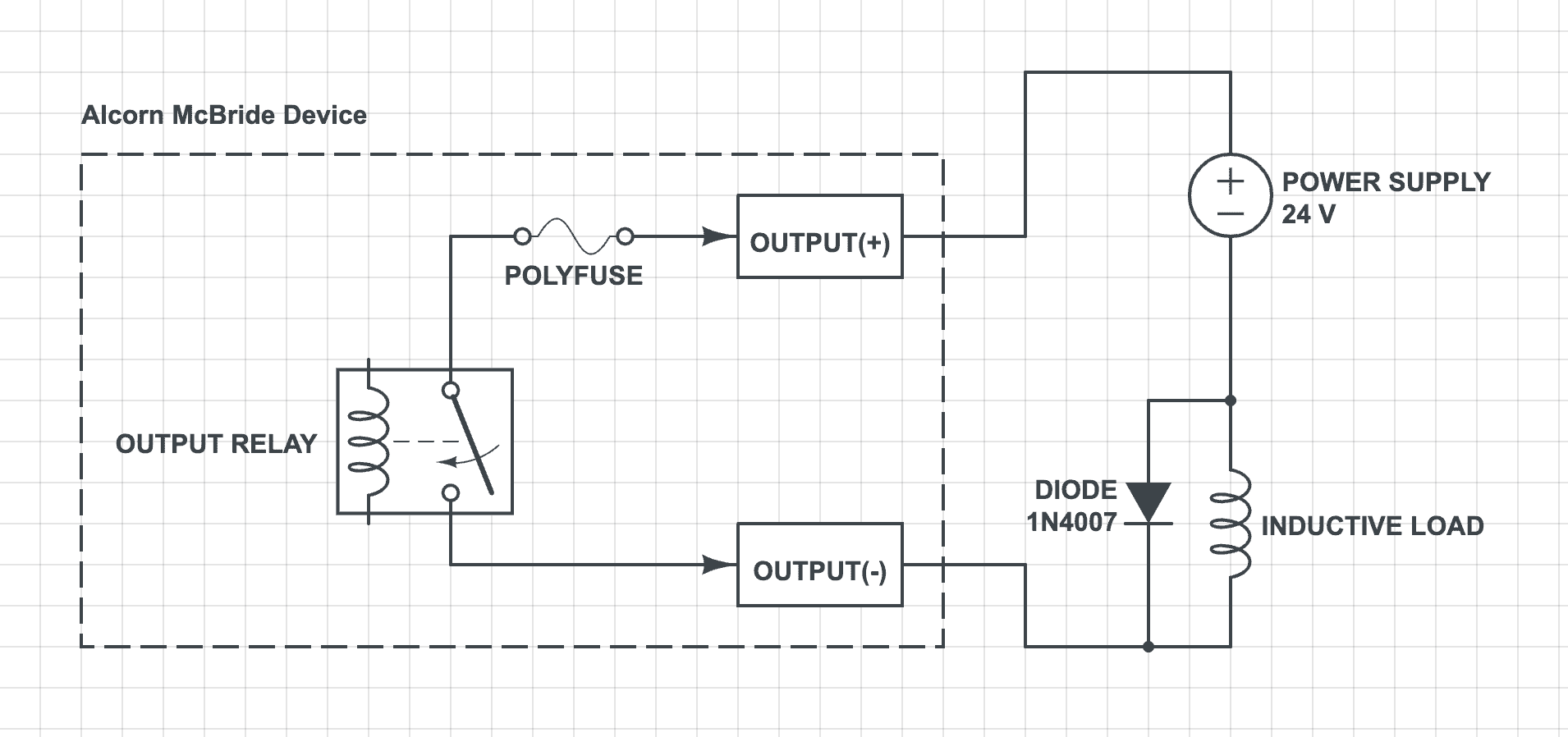
Inductive Load
Inductive loads have inductors, coils or transformers within the load. Relays, motors and mechanical actuators such as door latches, curtain controllers and other such devices are all inductive loads. These devices store electromagnetic energy to do work. When turned off, the energy stored within the device must be returned to a ground state or damage could occur to other devices in the system.
-
Connect the appropriate Output(+) pin on the Digital Outputs connector to the positive terminal of the external power supply.
-
Connect the corresponding Output(-) Return pin to the positive terminal of the device that is receiving the output signal.
-
Connect the negative terminal of the device that is receiving the output signal to the negative terminal of the external power supply.
-
Connect an appropriate 1N4000-series (1N4001-1N4007) diode across the load. Note the polarity of the diode in reference to the supply.