Warp and Blend
Welcome to the Warp and Blend Guide!
Warp and Blend has been a highly requested feature of our BinloopX and we’re excited to finally bring it to you with the latest version of WinScript Live. Warp and Blend is available on our BinloopX product.
Configure Script and Video Outputs
- Create a new script.
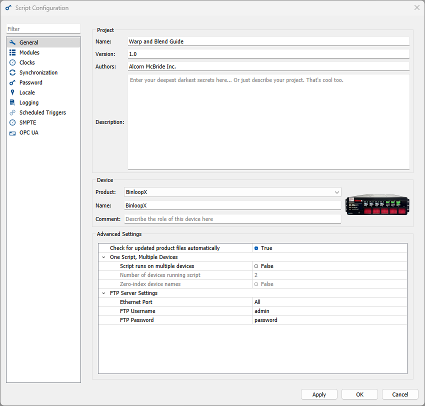
- In the Script Configuration dialog box, in the General section, in the Project section, enter your project details (Name, Version, Authors, and Description).
-
In the Device section, in the Product field, select BinloopX from the drop-down menu.
-
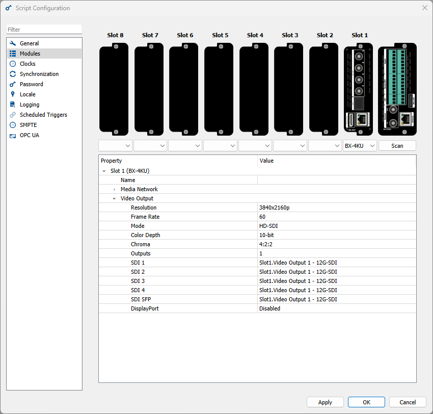
In the Modules section, in the dropdown menus beneath each slot you have populated on your BinloopX, select BX-4KU.
- In the section below the slots, expand the tree corresponding to the slot you which to configure, then expand the Video Output section.
-
In the Resolution field, select the resolution you wish to output, to a maximum of 4096x2160p.
-
Click OK.
Open Warp and Blend Dialog
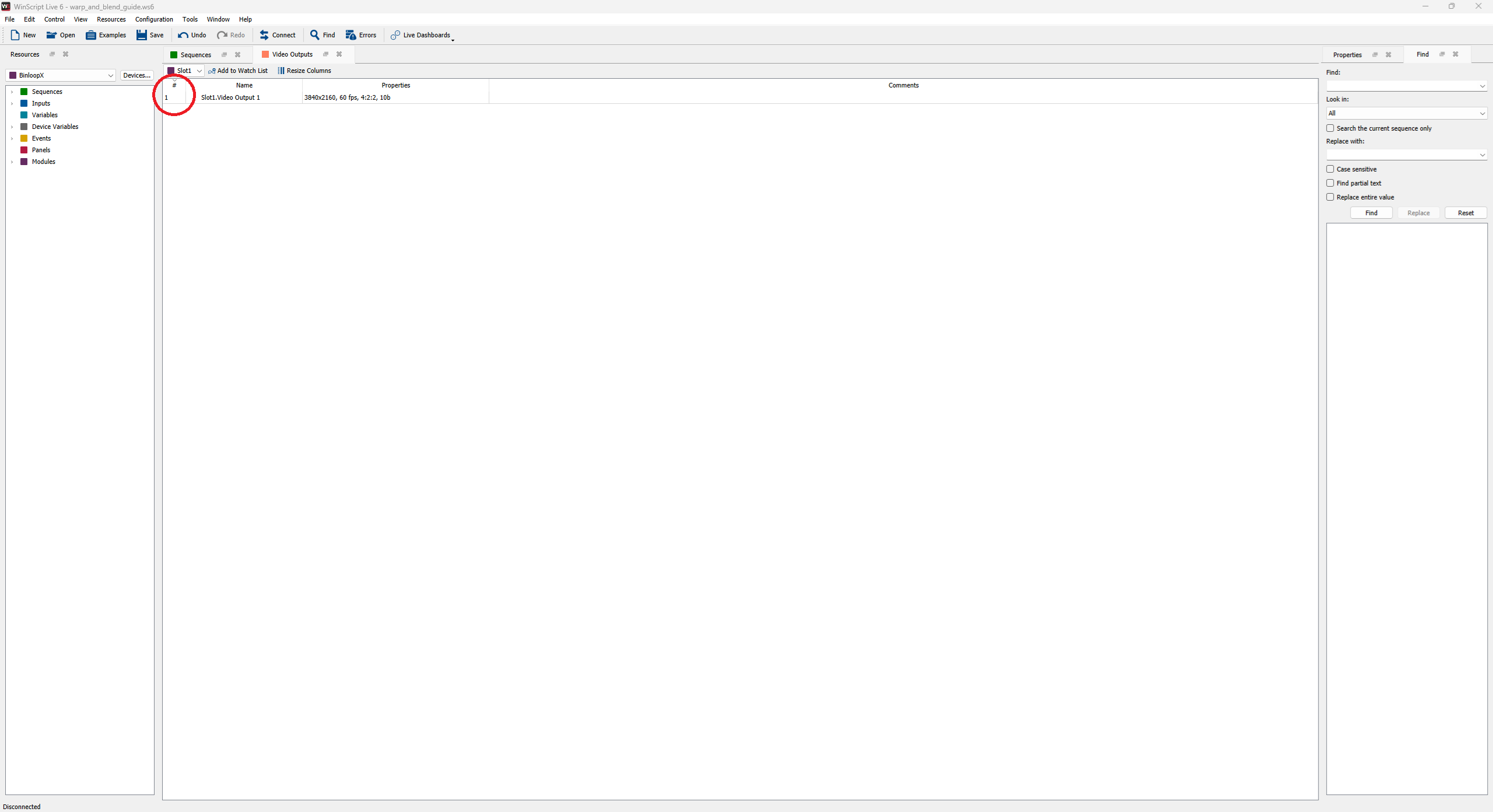
- In the WinScript application menu, click Resources → Video Outputs. This will open the Video Outputs resource view.
-
In the top left of this view, there is a dropdown that defaults to Slot1. In this dropdown, select the Slot for which you want to configure Warp and Blend.
-
Double click on in the # column on the line corresponding to the video output you wish to configure (shown in the red circle above). This will open the Warp and Blend dialog box.
Warp and Blend Dialog Box
At the top of the dialog box, three different options will be presented:
- Use MPCDI file on device
- Use MPCDI components on device
- Warp and blend with WinScript (default)
Each radio option is mutually exclusive.
Warning
If your MPCDI or PFM file contains invalid points (NaN), the BinloopX warp engine will extrapolate points to maintain a smooth blend through those points. If you intend for those points to show as black pixels, they should be included in the alpha blend/mask file.
Use MPCDI file on drive
Use this feature if you already have an MPCDI file you wish to use.
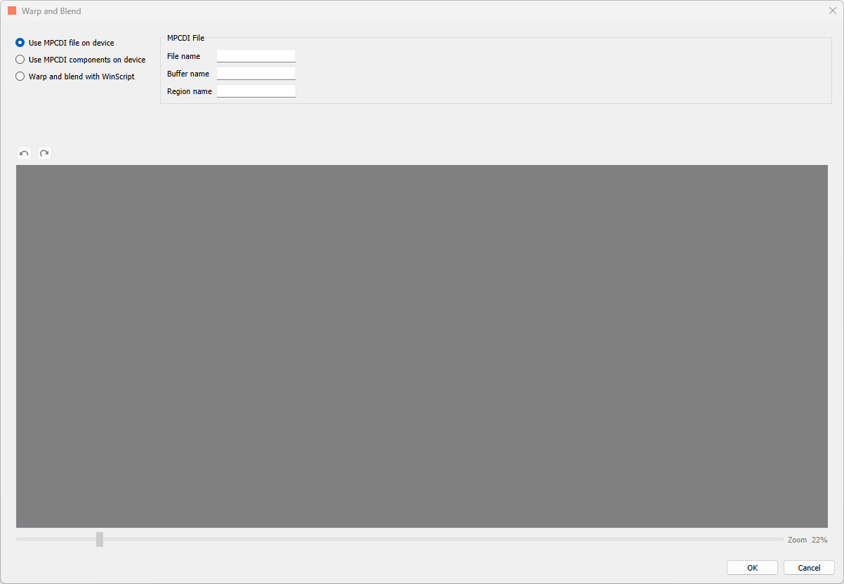
- In the MPCDI File section, in the File name field, enter the file name of your MPCDI file.
- In the Buffer name field, enter the name of the buffer you wish to use.
- In the Region name field, enter the name of the region you wish to output on this Video Output on this BX-4KU slot.
MPCDI files should be stored in the "warp" directory of the BX-4KU.
Use MPCDI components on device
Use this option if you wish to specify the components of an MCPDI file directly.
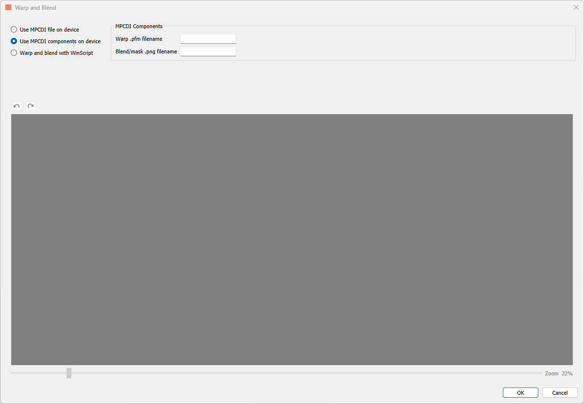
- In the MPCDI Components section, in the Warp .pfm filename field, enter the file name of your .pfm file.
- In the Blend/mask .png field, enter the file name of the blend/mask file.
- In the Region name field, enter the name of the region you wish to output on this Video Output on this BX-4KU slot.
PFM and PNG files should be stored in the "warp" directory of the BX-4KU.
Warp and blend with WinScript
The diagram below shows the features of Warp and blend with WinScript.
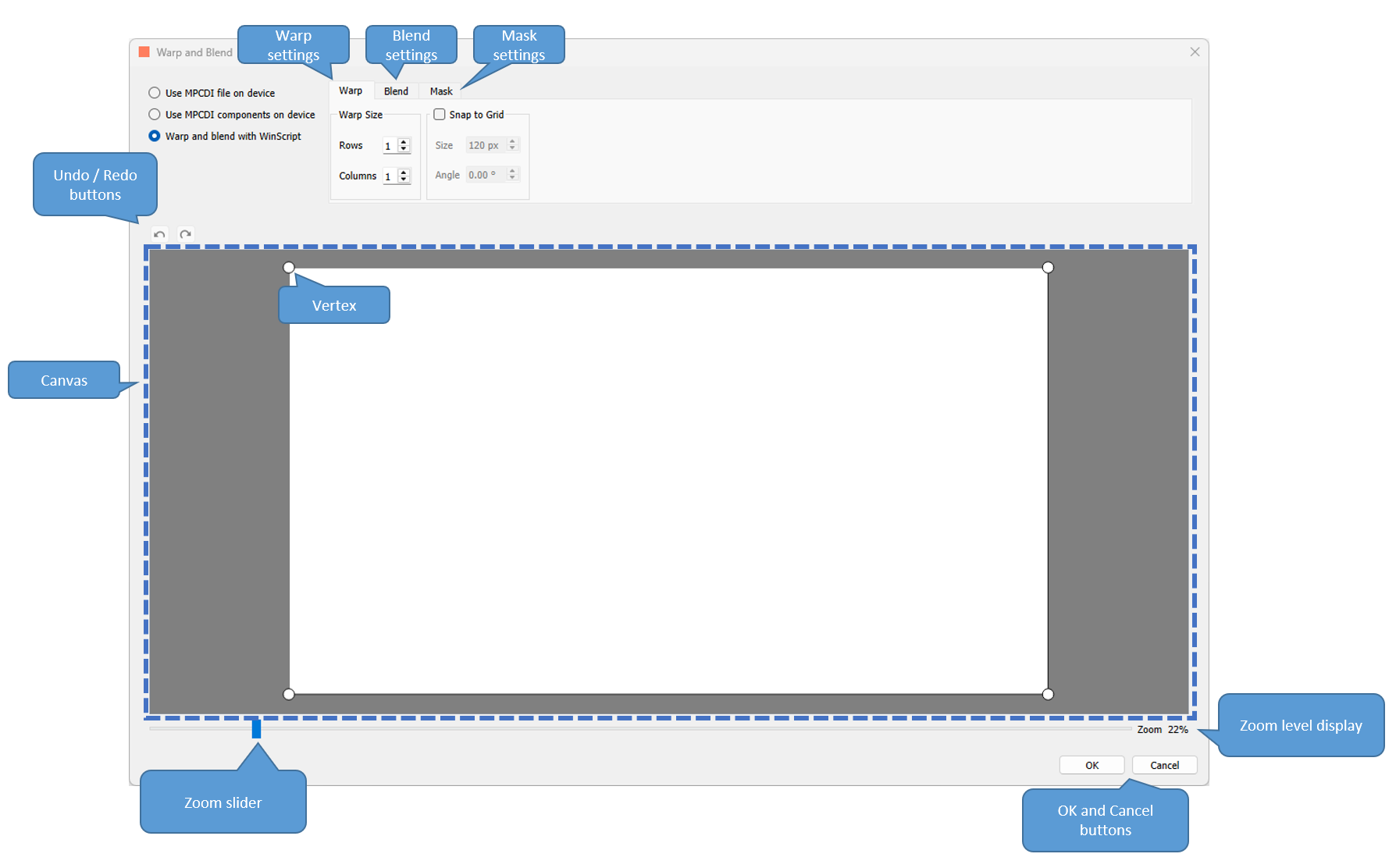
- Warp settings: warp size and snap to grid options for warp
- Blend settings: gamma, smoothness, and left, right, top and bottom settings for blend
- Mask settings: units, and left, right, top and bottom settings for mask
- Undo / redo buttons: undo and redo any settings change or vertex positioning
- Canvas: area where you will define your Warp mesh, Blend regions, and Mask edges
- Vertices inside the Canvas while on Warp settings
- Zoom slider and Zoom level display
- OK and Cancel buttons: click OK to save your settings, and Cancel to discard any changes
The following sections go into more detail about each of these features.
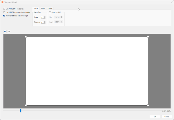
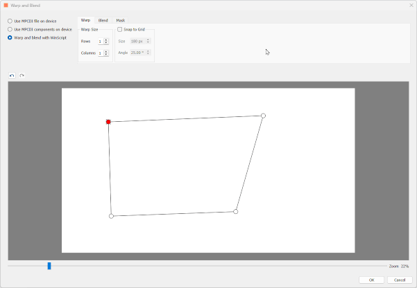
Warp
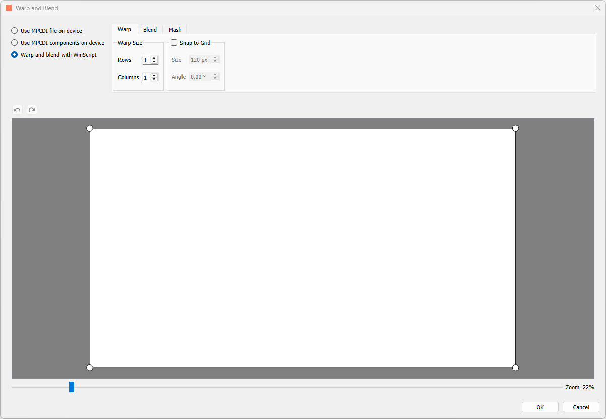
This feature allows you to reposition vertices to create a Warp mesh to apply to your output.
In the picture above, you can see a white area representing the output resolution of the BX-4KU. By default, each corner contains a white dot. These are the initial vertices. You can left click and hold to drag these vertices around one by one to create a warp. Lines between the vertices are bilinearly interpolated.
You can use ctrl + Z or ctrl + Y to undo or redo vertex positioning. You can also use the Undo and Redo arrows. In addition, you can select multiple vertices at once by dragging a box around them with your left mouse click button, or you can use control + left mouse click to select them. Clicking again anywhere in the dialog box will deselect the vertices. Additionally, you can use the arrow keys on your keyboard to move selected vertices by 1 pixel at a time. Lastly, you can move the vertices outside the white resolution area into the grey area as well. This effectively discards those pixels from the final output.
Warp Size
Beneath the Warp tab, there is a section called Warp Size. In this section, you can configure how many Rows and Columns your Warp mesh contains. Adding Rows and Columns will add a vertex at the intersection of any new Rows or Columns.
The default grid is 1 Row by 1 Column and the maximum is 64 Rows by 64 Columns. Each incremental step is a power of 2 (2, 4, 8, 16, 32, 64). When you decrease the number of Rows or Columns, any vertex on a Row or Column that is removed is deleted, and it’s position is reset to default if you then create more Rows or Columns later.

Note
More complicated warp meshes may take longer to apply when making changes in live mode.
Snap to Grid
Selecting this setting will create a grid to which you can snap your vertices.
This Size setting determines how far apart points on the grid are. The default is 120 px, meaning that with an output of 3840x2160, you get a grid of 32 across and 18 down. Using the up and down down arrows will increment and decrement by 5 pixels, or you can type in a number. The bigger the Size, the further apart each point in the grid is; the smaller the Size, the closer together each point is. The maximum Size of the grid will be set to the maximum output resolution.
The Angle setting will allow you to rotate the grid. You can change the angle by using the up and down arrows to increment and decrement the angle by 5°, or you can type in the number of the angle you wish to use. The range of angles you can use is -90° to +90°.
Lastly, if you uncheck the Snap to Grid option, the previous Size and Angle settings are preserved, and each vertex of your Warp mesh will retain it’s position.
Other Details
The Warp engine in BinloopX applies warp meshes with vertices every 8 pixels (except for 4096x2160 output resolution, where vertices are every 16 pixels). Pixels in between vertices are bilinearly interpolated for a smooth output. Higher resolution MPCDI or PFM files can be used and they will be automatically resampled for compatibility with our warp engine. Lower resolution warps are also fine, they'll be upsampled automatically.
Blend
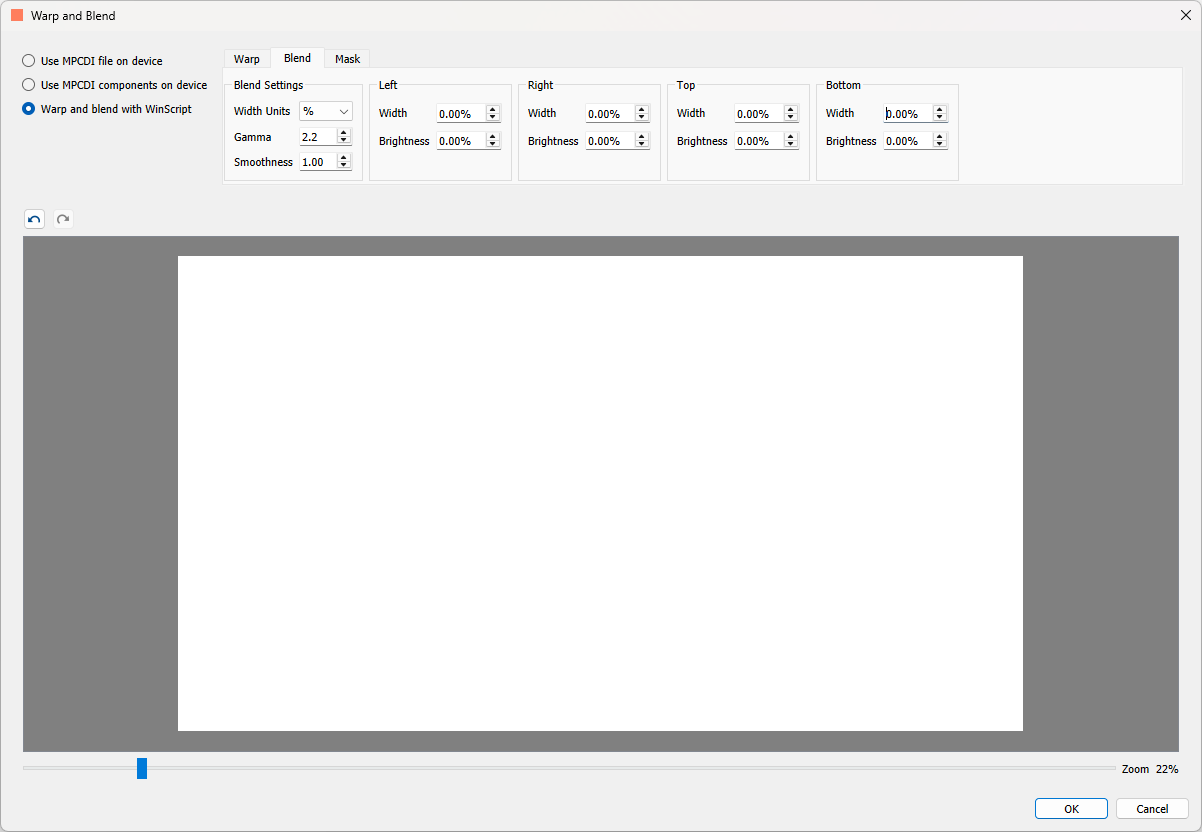
This feature allows you to define the Gamma, Smoothness, and directions of your Blend to apply to your output.
Left, Right, Top, Bottom
Each of these sections has a setting for Width and Brightness. The Width determines how far across the output the Blend applies, starting from the edge in the section name. For example, setting the Width in the Right section to 50% will apply a Blend starting from the right hand side of the output, and going halfway across the output. The minimum is 0.00 %, representing no Blend, and the maximum is 100.00 %, representing a blend across the entire output from that direction. Using the up and down arrows will increase and decrease the width by 5.00 % at a time, or you can enter a number into the field.
The Brightness setting determines the output brightness in the Blend. 0.00 % represents the pixels in that region completely blended, with 100.00 % representing no Blend. Using the up and down arrows will increase and decrease the width by 5.00 % at a time, or you can enter a number into the field.
The Width units setting can be either percentages (%) or pixels (px). This determines the units for the Width settings in the Left, Right, Top, and Bottom sections. Swapping between the two units will convert one to the other.
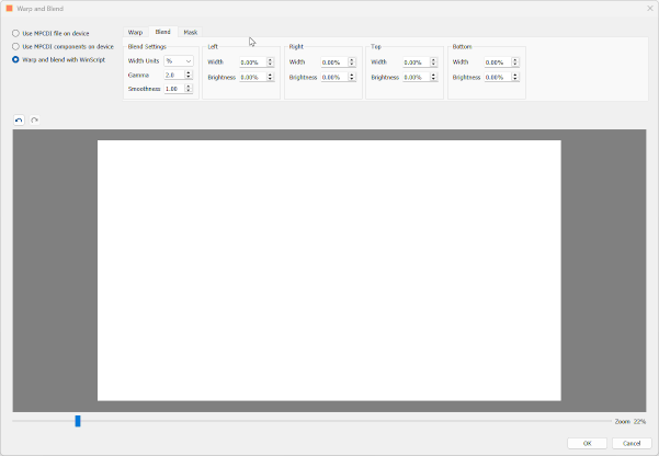
Blend Settings
The Gamma setting determines the gamma curve of the Blend. Generally, you want this to match the gamma setting of your projector - though fine adjustments are usually needed to get a perfect blend. The default value is 2.2, with a minimum of 1, and a maximum of 3.0. The arrow keys increment and decrement the value by 0.1.
The Smoothness setting determines the gradient of the transition of the Blend. The lower the Smoothness, the harsher the gradient, and the higher the Smoothness, the smoother the gradient. The default Smoothness is 1.0, with a maximum of 1.00, and a minimum of 0.00.
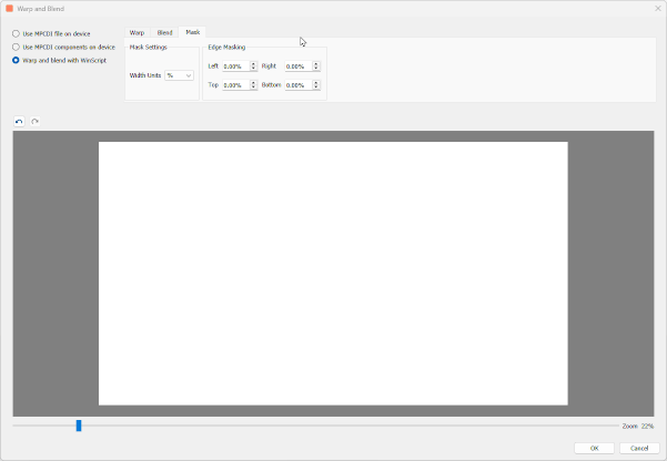
Mask
This feature allows you to define areas from each directions that are masked out of your output. This feature works much like the Blend feature, but without gradients.
In the Edge Masking section, each setting, Left, Right, Top, and Bottom, determine how far into the output from that direction to mask. The minimum value is 0.00 %, corresponding to no mask from that direction, to 100.00 %, corresponding to a completely masked out output.
The Width units setting can be either percentages (%) or pixels (px). This determines the units for the Width settings in the Left, Right, Top, and Bottom settings. Swapping between the two units will convert one to the other.
Other Features
Undo/Redo
Undo and Redo arrows are included to Undo and Redo all settings changes, including repositioning vertices in the Warp mesh. Ctrl + Z and ctrl + Y are also supported.
Zoom and View Controls
The slider below the Canvas can zoom into and out of the view to enable more granular editing of the Warp, Blend, or Mask. The Zoom % is displayed to the right of the slider. When you are zoomed in, scroll bars appear along the right and bottom of the Canvas. The default zoom is 22 %, the maximum zoom out is 1%, and the maximum zoom in is 200 %.
You can also use the mouse scroll wheel to scroll vertically, and holding the Alt key will allow the mouse will to scroll horizontally. Holding the shift key when scrolling in either direction will scroll with less granularity.
Note
The zoom level also determines how far each vertex moves when you use the arrow keys to reposition during Warp. The further zoomed in you are, the more granularly the vertex moves.
OK and Cancel
Clicking the OK button in the bottom right of the menu will save all your Warp and Blend changes (temporarily, you will still need to save the script itself). Clicking the Cancel button will discard all changes since the last time the OK button was clicked.
Editing In Live Mode
While connected to your BinloopX in Live Mode, any changes made to the Warp, Blend, or Mask settings will immediately apply to the output of your BinloopX. This means you can edit vertices on the Warp mask, Width or Gamma or Smoothness of your Blend mask, or change the Mask regions all on the fly and see the updates in your output in realtime.
Editing Multiple Video Outputs
Each video output has its own set of Warp and Blend settings. To edit another video output, go back to the Video Outputs resource view and choose the video output you'd like to edit.