Modbus TCP
Alcorn McBride devices have native support for Modbus TCP, an ethernet-based protocol commonly used for communication between industrial devices such as PLC's, field I/O, gateways, and other devices. Specifically, you can make a Alcorn McBride device be a Client, which is the device that initiates communication and requests data. For example, that data could be PLC tag values or discrete input status.
Two types of Modbus Client support are available: Modbus Polling and Slave I/O. Modbus polling is the more generic protocol - it allows you to set up a series of Device Variables within WinScript which will be automatically updated at the specified polling rate. Slave I/O is a more specialized version of Modbus Client support, it allows Modbus enabled I/O devices to seamlessly appear along side the integrated discrete inputs and outputs of your Alcorn McBride device, greatly expanding the built-in I/O count. These Inputs and Outputs are syncronized for the user at the specified polling rate and can be treated like native Inputs or Outputs.
Automatic Read/Write Polling
As of WinScript Live v6.2.0-b9 and newer, the Modbus product file supports automatic polling.
The following Modbus data types are supported:
- Coils
- Discrete Inputs
- Input Registers
- Holding Registers (16 and 32 bits)
Arrays are supported, but the data on the Modbus device must be continuous for each array you add to your script. For example, if an integer array in Winscript is configured to poll holding registers of a Modbus device starting at address 0, then the first element of the array corresponds to address 0, the second element corresponds to address 1, and so on.
Integer variables in Winscript use 32 bits by default, but only the least significant 16 bits will be filled from the Modbus device. When using the 32-bit Holding Register data type, two adjacent 16-bit holding register values will be concatenated into one 32-bit Winscript integer.
Enabling Automatic Polling
With a script opened in WinScript, navigate to "Resources" at the top of the window, then select "Devices." Select "New" to add a Modbus device, using the Modbus manufacturer and model:

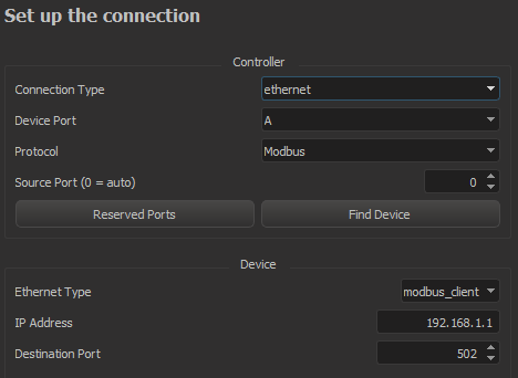
On the next screen, select "modbus_client" as the protocol:

Then, navigate to "Resources" at the top of the WinScript window and select "Device Variables." In the device dropdown, select the name of your Modbus device and click "New." Follow the instructions in the variable wizard to make your device variable sync with the data type on the Modbus Server. You should see new entries in the Device Variables list with Modbus info in the "Details" column. See arrReadHoldingRegs and arrWriteHoldingRegs below:

The variables you create in this wizard will automatically sync with the Modbus device at the configured addresses. Variables with read access will update in WinScript automatically on the interval specified in the "Poll Every" box. Variables with write access will cause a Modbus write command to be sent on the frame in which they are written in WinScript.
Best results have been achieved when using two device variable arrays: one for reading from the Modbus Server and one for writing to the Modbus Server.
NOTE: Many Modbus clients exhibit a turnaround time of 10ms or more. If you read and write to the same modbus device within the same frame, you may observe 1-2 frames of jitter at higher frame rates.
Slave I/O
Any IO device capable of using Modbus TCP can have its I/O controlled as if it was I/O internal to the show controller, but it does require a product file be written for the device. We have product files available for several commonly used devices, such as the Beckhoff BK9100 and Advantech Adam-6000 series IO. Please contact support if you have a different Modbus TCP I/O device you would like to use with Slave I/O.
The following example demonstrates how to setup a Beckhoff BK9100. 1. Add the IO module to the "Devices" list by clicking the "New" button in the "Devices" window.
-
Enter a name such as "MyBeckhoff".
-
Select the Make, Model and version of the I/O.
-
Set the protocol to "Slave IO"
-
Select the controller Ethernet port and enter the I/O device's IP address
-
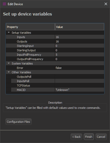
Enter the number of "Inputs" and "Outputs" into the setup fields. The "StartingInput" and "StartingOutput" are typically 0. Set these only if controlling a sub-section of the I/O on a particular control module. For example, if you only wanted to watch inputs 3-12 on a module that had 0-12 available.

-
The "InputPollFrequency" can be set to as little as 1 frame. If you have greater than nine devices that are setup to poll inputs, you must decrease the polling to 2 frames or more.
-
The "OutputPollFrequency" is typically set to zero. This does not mean that the outputs will never be polled. They will be polled on startup and after any command is sent to change the output’s status. (ie: after an "On", "Off" or "Toggle" command). If you prefer more constant polling, a recommended value would be 15 frames.
-
-
Click "Finish." Your IO will now show up in the "Inputs" and "Outputs" lists.
-
Go to "Resources" -> "Inputs" and select the device (in this example: "MyBeckhoff") to view the inputs list.