Hardware Information
Overview
The V4X has an assortment of dedicated hardware for the purpose of configuration, status monitoring, and interfacing to other hardware. This section covers these features in more detail.
Zone Status LEDs
On the V-Page VP4X, each zone select pushbutton has an integrated tri-color LED. Starting with Plugin v2.15.00, you now have the option to select the following Paging Mode States: Standard, APS, or Custom. Prior to Plugin v2.15.00, all V-Pages exhibited the Standard Mode functionality. Standard Mode is still the default mode selected while setting up a V-Page VP4X. To change this mode, adjust the Paging Mode option in the Plugin Properties tab.
| Description | Standard Mode LED States | APS Mode LED States | Custom Mode LED States |
|---|---|---|---|
| Idle Zone Available | Off | Plugin Configurable | |
| Idle Zone Selected | Plugin Configurable | ||
| Active Zone Available (Can Interrupt) | Plugin Configurable | ||
| Active Zone Selected | Plugin Configurable | ||
| Zone Busy (Unvailable to Select) | Plugin Configurable | ||
| Button Unused | Off | Off | Off |
| Link Active | |||
| Unconfigured/Unable to Connect to Q-SYS Core | |||
| Firmware Update Mode |
NOTE: These indicators can be overridden using the Breakaway feature of the V-Page plugin. This allows you to take manual control of the LED status using IO pins in Q-SYS designer.
DIP Switches
The configuration DIP switches are located on the side of the V-Page. Changing the states of these switches, either during power-up or normal operation, can alter the behavior of the V-Page. The default position for all the switches for normal operation is OFF (UP).
The V-Page can power up in one of the following modes (based on switches configuration):
- Normal Mode
- Factory Test Mode
- Firmware Update Mode
During power up, the state of some switches (ON or OFF) may result in action. During runtime, toggling the DIP switch (OFF => ON => OFF) may perform a specified action. See the descriptions below.
DIP Switch 1: Link Mode
Runtime
OFF => ON => OFF: Activate/deactivate Link Mode. Toggle once to activate, toggle again to deactivate. Link Mode will also exit on successful completion or will auto-exit after 60 seconds (default).
Link Mode can be used in conjunction with Q-SYS to assign station ID, static IP/Port and Q-SYS feedback information to the V-Page. In a sense, this pairs the V-Page with a specific Q-SYS Core.
While Link Mode is active, the green LEDs will illuminate one at a time in a sequential chasing pattern.
DIP Switch 2: Firmware Update Mode / Reset Factory Defaults
Power Up
ON: Enter Firmware Update mode. In this mode, the V-Page disregards all other settings and all other DIP switches and uses a default IP of 192.168.0.254. Web server serves up Firmware Update page. For a detailed explanation on updating V-Page firmware, see the Firmware Update section. To exit Firmware Update Mode, return the switch to OFF position and perform a power cycle.
OFF: Default state of the switch for normal operation.
NOTE: It’s advised to use AMI Terminal to invoke the firmware update. The V-Page will enter the firmware update mode on the last known IP instead of fixed 192.168.0.254.
Runtime
OFF => ON => OFF: Perform factory defaults (in normal operation mode only). All LEDs will light up solid RED for a few seconds, then the V-Page will reset to defaults. Any stored settings will be erased from non-volatile memory and restored to their factory defaults. This affects Dante settings as well.
NOTE: Loading Factory Defaults will erase all V-Page settings!
DIP Switch 3: Factory Test Mode
Power Up
ON: Puts the V-Page into Factory Test Mode for testing purposes only. Factory Test Mode is mainly used for troubleshooting. It is NOT a requirement to program the V-Page as all the parameters can be programmed while operating in the normal mode. While in Test Mode, V-Page will not fully operate as a paging station.
NOTE: Firmware Update DIP Switch 2 must be OFF!
OFF: Default state of the switch for normal operation.
DIP Switch 4: Spare (unused)
This DIP Switch is currently not in use.
Power Up/Runtime
ON: Not in use.
OFF: Default state of the switch for normal operation.
Connectors
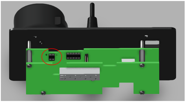
Power
An external power input is provided if you do not use Power-Over-Ethernet (PoE) (circled in red below). The Power Connector pinout is shown below (looking from the front of the connector). Polarity is also labeled on the bottom of the PCB.
The power input accepts 5 VDC to 37 VDC at 1 A max.
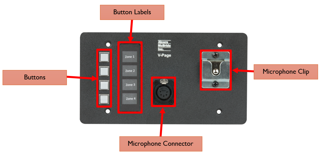
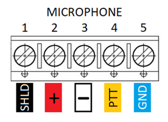
Microphone Input
The microphone connector pinout is shown below. Pin numbers are also printed on the bottom of the PCB.
This input is designed for dynamic microphones and also includes a Push-to-Talk (PTT) input.
This connector on the V-Page VP4X comes pre-wired to a 5-pin XLR connector mounted on the front of the unit that is designed to interface to the included microphone. If you wish to remotely wire a microphone, this connector can be removed and replaced with cover plate that is included in the product packaging.
Here is the pinout of the 5-pin XLR connector harness:
| Wire Color Code | Phoenix Connector | 5-Pin XLR (Female) |
|---|---|---|
| Black | Pin 1 | Pin 1 |
| Red | Pin 2 | Pin 2 |
| White | Pin 3 | Pin 3 |
| Yellow | Pin 4 | Pin 4 |
| Blue | Pin 5 | Pin 5 |
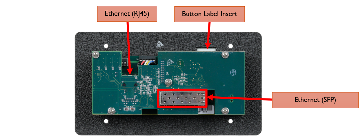
Ethernet (RJ45)
A standard RJ-45 ethernet connector is used for the network connection and PoE.
Ethernet (SFP)
A Small Form-factor Pluggable (SFP) transceiver connector is available to provide support for a fiber-optic alternative to the RJ45 port. Both Single-Mode and Multi-Mode modules are compatible. Make sure that the same SFP module model is used on both ends of the fiber optic connection to ensure compatibility.