Hardware Information
Overview
RideAmp has quite an assortment of dedicated hardware for the purpose of configuration, status monitoring, and interfacing to other hardware. This section covers these features in more detail.
Indicator LEDs
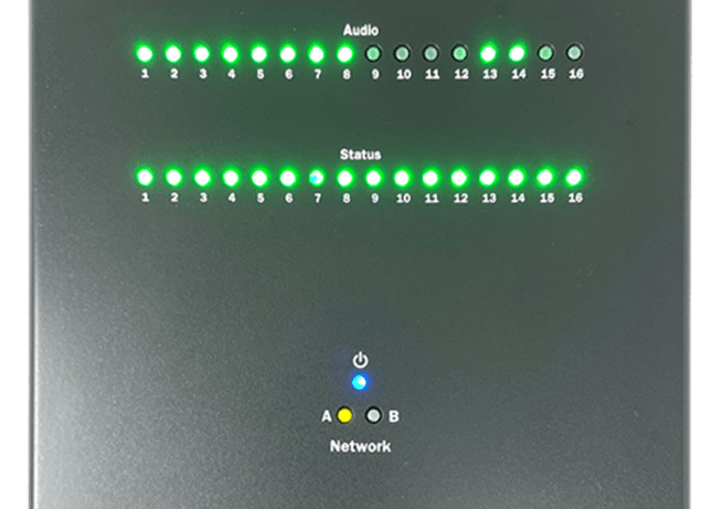
The top-panel of RideAmp has a full set of indicator LEDs to provide an overall status of different features of the device.
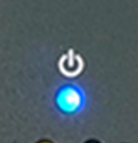
Power
| LED State | Description |
|---|---|
| OFF | No Power |
| DC Power Applied |
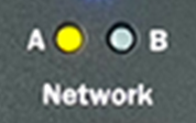
Network
These indicators display both network link and activity for all of the Control and Network Audio ethernet ports.
| LED State | Description |
|---|---|
| OFF | No network link |
| Network link active - no network activity detected | |
| Network link active - network activity detected |
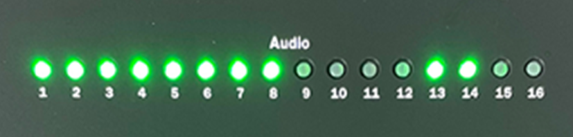
Audio
These indicators display the signal status of each audio input.
| LED State | Description |
|---|---|
| OFF | OK - no audio signal detected |
| OK - active audio signal | |
| Not ready - initializing | |
| Audio Output is MUTED |
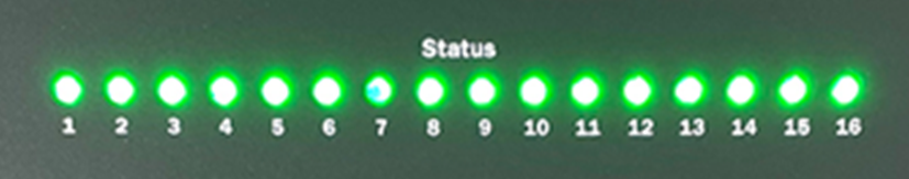
Status
These indicators display the operational status of each amplifier channel.
| LED State | Description |
|---|---|
| OFF | Amplifier not ready - initializing |
| Amplifier OK | |
| Amplifier WARNING | |
| High temperature | |
| Single fan failure | |
| Bootloader Mode ENABLED (DIP Switch #2) | |
| Amplifier FAULT | |
| Critical temperature | |
| Dual fan failure | |
| Shorted speaker output (protect) | |
| Low power voltage | |
| Audio clock lost | |
| Factory Test Mode ENABLED (DIP Switch #1) | |
| Amplifier OK, recovered from Warning | |
| Amplifier OK, recovered from Fault |
Connectors
Speaker Outputs
This is where you connect speakers to the RideAmp. You can wire up to 16 discrete channels of speakers at up to 30 W each, or you can bridge each channel pair to achieve up to 60 W.
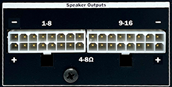
NOTE: NEVER CONNECT ANY OF THE SPEAKER OUTPUTS TO GROUND. THE AMPLIFIER WILL IMMEDIATELY GO INTO AN OVERCURRENT FAULT CONDITION.
Connector Information
| Speaker Connector | |
|---|---|
| Connector Type | 2x8 Molex Mini-Fit Jr. |
| Mating Plug | Molex 0039012160 |
| Mating Pins | Molex 0039000185 |
| Recommended Wire | 16 AWG Stranded |
Pinouts
Plug pinout (Wire-Side View)
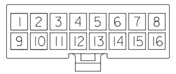
Non-Bridged Wiring
The following pinouts apply when using speaker outputs individually for up to 30 W operation.
| Speakers (Non-Bridged - 30 W) | |||
|---|---|---|---|
| Speaker 1 (-) | 1 | Speaker 9 (-) | 1 |
| Speaker 1 (+) | 9 | Speaker 9 (+) | 9 |
| Speaker 2 (-) | 2 | Speaker 10 (-) | 2 |
| Speaker 2 (+) | 10 | Speaker 10 (+) | 10 |
| Speaker 3 (-) | 3 | Speaker 11 (-) | 3 |
| Speaker 3 (+) | 11 | Speaker 11 (+) | 11 |
| Speaker 4 (-) | 4 | Speaker 12 (-) | 4 |
| Speaker 4 (+) | 12 | Speaker 12 (+) | 12 |
| Speaker 5 (-) | 5 | Speaker 13 (-) | 5 |
| Speaker 5 (+) | 13 | Speaker 13 (+) | 13 |
| Speaker 6 (-) | 6 | Speaker 14 (-) | 6 |
| Speaker 6 (+) | 14 | Speaker 14 (+) | 14 |
| Speaker 7 (-) | 7 | Speaker 15 (-) | 7 |
| Speaker 7 (+) | 15 | Speaker 15 (+) | 15 |
| Speaker 8 (-) | 8 | Speaker 16 (-) | 8 |
| Speaker 8 (+) | 16 | Speaker 16 (+) | 16 |
Bridged Wiring
The following pinouts apply when bridging speaker outputs for up to 60 W operation. Bridging is configured within the RideAmp Utilities application.
| Speakers (Bridged - 60 W) | |||
|---|---|---|---|
| Speaker 1 (-) | 1 & 9 | Speaker 9 (-) | 1 & 9 |
| Speaker 1 (+) | 2 & 10 | Speaker 9 (+) | 2 & 10 |
| Speaker 3 (-) | 3 & 11 | Speaker 10 (-) | 3 & 11 |
| Speaker 3 (+) | 4 & 12 | Speaker 10 (+) | 4 & 12 |
| Speaker 5 (-) | 5 & 13 | Speaker 11 (-) | 5 & 13 |
| Speaker 5 (+) | 6 & 14 | Speaker 11 (+) | 6 & 14 |
| Speaker 7 (-) | 7 & 15 | Speaker 12 (-) | 7 & 15 |
| Speaker 7 (+) | 8 & 16 | Speaker 12 (+) | 8 & 16 |
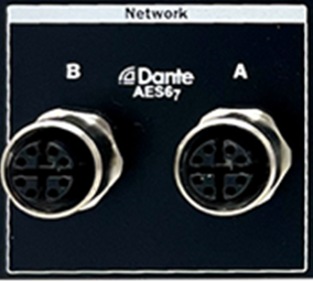
Network
The RideAmp provides a total of two M12 X-Coded network ports. These ports are devoted to a 16 input (16x0) network audio interface that supports the AES67 and Dante standards. These ports also pass back important status information via the Dante/AES67 link to RidePlayer for monitoring amplifier health.
Two connectors are provided for each of these network connections to allow up to eight RideAmp units to be daisy-chained without the need for an external M12 Ethernet switch.
Connector Information
| Network Connector | |
|---|---|
| Connector Type | M12 X-Code Female |
| Mating Plug | M12 X-Code Male |
Power
RideAmp is designed to accept either a 12 VDC or 24 VDC power source. An inline automotive blade fuse (25 A/80 V) is accessible on the RideAmp side panel. Voltage levels are electronically monitored, and low voltage conditions can be reported back via the network audio connection to RidePlayer.
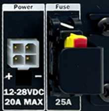
Connector Information
| Power Connector | |
|---|---|
| Connector Type | 2x2 Molex Mini-Fit Jr. |
| Mating Plug | Molex 0039012040 |
| Mating Pins | Molex 0039000185 |
| Recommended Wire | 16 AWG Stranded |
Pinouts
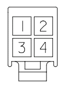
| Power Connector | |
|---|---|
| DC Power (+) | 1 |
| DC Power (-) | 2 |
| DC Power (+) | 3 |
| DC Power (-) | 4 |
USB
RideAmp is equipped with a standard USB-C connector which is used to communicate with a PC laptop running the RideAmp Utility Application. This port can also be used to perform firmware updates when necessary.

Configuration Switches
These configuration switches can be used to apply different modes and actions, such as resetting factory defaults. DOWN is the ON position.
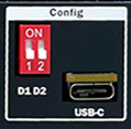
Switch D1: Reset Factory Defaults
| D1 | |
|---|---|
| Off (Up) | Normal operation |
| On (Down) | Reset Factory Defaults |
Switch D2: Bootloader Mode
| D2 | |
|---|---|
| Off (Up) | Normal operation |
| On (Down) | Force Bootloader Mode |